Difference between revisions of "KAmodRPi PwrRELAY4"
(Created page with "__jzpdf__ ===== Introduction ===== [https://kamami.pl/moduly-z-przekaznikami/583785-modul-4-przekaznikow-dla-raspberry-pi.html KAmodRPiRELAY4] is a universal functional expand...") |
|||
| Line 1: | Line 1: | ||
__jzpdf__ | __jzpdf__ | ||
| + | |||
===== Introduction ===== | ===== Introduction ===== | ||
[https://kamami.pl/moduly-z-przekaznikami/583785-modul-4-przekaznikow-dla-raspberry-pi.html KAmodRPiRELAY4] is a universal functional expander for Raspberry Pi and Raspberry Pi+ computers, equipped with four electromechanical relays that are switched on by optoisolators with GPIO outputs and allow, for example, remote lighting control, heating switching and other tasks requiring remote access. | [https://kamami.pl/moduly-z-przekaznikami/583785-modul-4-przekaznikow-dla-raspberry-pi.html KAmodRPiRELAY4] is a universal functional expander for Raspberry Pi and Raspberry Pi+ computers, equipped with four electromechanical relays that are switched on by optoisolators with GPIO outputs and allow, for example, remote lighting control, heating switching and other tasks requiring remote access. | ||
Latest revision as of 08:43, 24 October 2023

Contents
Introduction
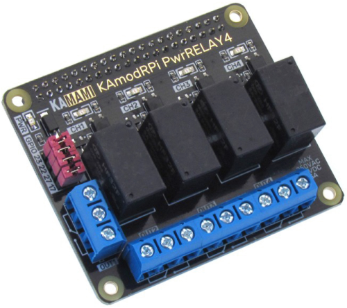
KAmodRPiRELAY4 is a universal functional expander for Raspberry Pi and Raspberry Pi+ computers, equipped with four electromechanical relays that are switched on by optoisolators with GPIO outputs and allow, for example, remote lighting control, heating switching and other tasks requiring remote access.
Basic features and parameters
- Compatibility with minicomputers Raspberry Pi 1 B+, Raspberry Pi 2 and Raspberry Pi 3, Raspberry Pi 3 model B+ and Raspberry Pi 4 model B.
- Four relay outputs
- Output states monitored by LED
- ARK screw terminals
- Jumpers enabling disconnection of the relay from the GPIO port
Relay outputs
- Four SPDT outputs
- Relays switched with optocouplers
- Maximum switchable voltage: 250 VAC/30 VDC
- Maximum switching current (resistive load): 10 A
- Recommended maximum load currents: 3 A
Standard equipment
| Code | Opis |
|---|---|
| KAmodRPi PwrRELAY4 | KAmodRPi PwrRELAY4 module |
| Mounting kit | A set of screws and spacers enabling the attachment of the shield to the Raspberry board |
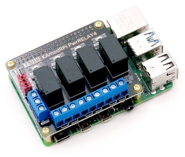
KAmodRPi PwrRELAY4 overlay placed on the Raspberry Pi and attached with spacers and screws
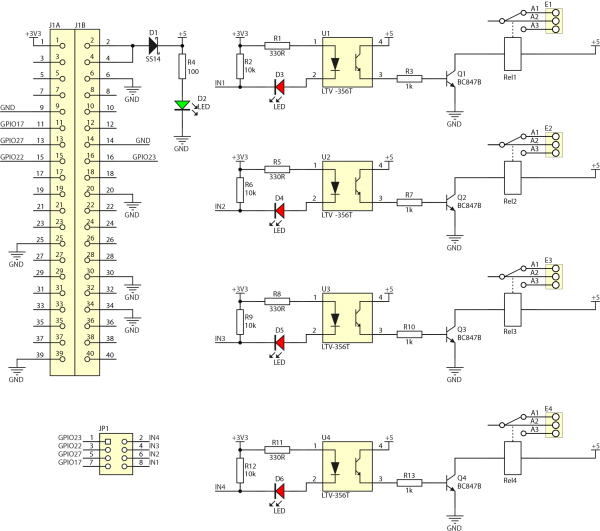
Schematic
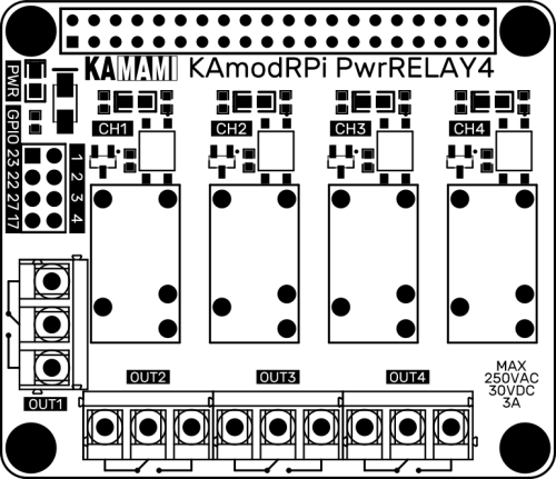
View of board
Assignment of outputs to the GPIO lines of the RaspberryPi computer
| Raspberry Pi pinout | KAmodRPi PwrRELAY4 relay |
|---|---|
| GPIO23 | OUT1 |
| GPIO22 | OUT2 |
| GPIO27 | OUT3 |
| GPIO17 | OUT4 |
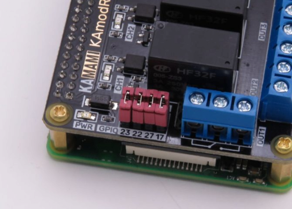
The GPIO line outputs are connected to the control circuit via a jumper, which allows you to disconnect the appropriate pins if necessary. Additionally, switching on the relay is signaled by the lighting of the LED on the appropriate channel.
Jumpers connecting the Raspberry Pi pins with the circuits that turn on the relay.
