Difference between revisions of "Nettemp Pi Hat"
(→Podstawowe cechy i parametry) |
Anna Kubacka (talk | contribs) |
||
| (5 intermediate revisions by 3 users not shown) | |||
| Line 1: | Line 1: | ||
| − | ====== | + | __jzpdf__ |
| − | [https://kamami.pl/kamod-kamami/559377-nettemp-pi-hat-modul-nettemp-dla-komputera-raspberry-pi.html Nettemp Pi Hat] to | + | ====== Description ====== |
| + | [https://kamami.pl/kamod-kamami/559377-nettemp-pi-hat-modul-nettemp-dla-komputera-raspberry-pi.html Nettemp Pi Hat] is a module that allows to connect eight trees of sensors with I2C/1-Wire interface and control of four relays outputs. Thanks to the extension board is possible to build in an easy way e.g. multipunkt temperature controller. | ||
<center> | <center> | ||
| − | [[ | + | [[File:Nettemp_Pi_Hat.png|none|600px|thumb|center]] |
</center> | </center> | ||
| + | |||
| + | ===== Basic features and parameters ===== | ||
| + | *Compatibility with NETTEMP software | ||
| + | *Extension board for Raspberry PI (version 3/2B/B+) | ||
| + | *Possibility of connection eight separate trees of sensors with I2C/1-Wire interface | ||
| + | *Module is supplied with minicomputer | ||
| + | *Embedded UART-USB converter (based on chip CP2102 from Silicon Labs) | ||
| + | *Embedded four relays with NO/NC outputs | ||
| + | *Load is connected by screw terminals | ||
| + | *Maximum load of relay pins: 3A / 250VAC | ||
| + | *Embedded real-time clock (M41T00S chip from STMicroelectronics) | ||
| + | *Embedded battery holder for RTC support | ||
| + | *Embedded buzzer | ||
| + | *Embedded connector allows to add a minicomputer without any wires | ||
| + | *Embedded pin connector GPIO 28-pin allows e.g. to add TFT display | ||
| + | *Mounting holes for Raspberry PI fastening | ||
| + | *Module size: 146mm x 80mm x 20mm | ||
| − | ===== | + | ===== Standard equipment ===== |
| − | |||
| − | |||
| − | |||
| − | |||
| − | |||
| − | |||
| − | |||
| − | |||
| − | |||
| − | |||
| − | |||
| − | |||
| − | |||
| − | |||
| − | |||
| − | |||
| − | |||
<center> | <center> | ||
{| class="wikitable" style="width: 1000px;" | {| class="wikitable" style="width: 1000px;" | ||
|- | |- | ||
| − | ! style="text-align: center;"| | + | ! style="text-align: center;"|Code |
| − | ! style="text-align: center;"| | + | ! style="text-align: center;"|Description |
|- | |- | ||
| style="text-align: center;"|<b>Nettemp Pi Hat</b> | | style="text-align: center;"|<b>Nettemp Pi Hat</b> | ||
| − | | style="text-align: | + | | style="text-align: left;"| |
| − | * | + | *Assembled and launched module |
|} | |} | ||
</center> | </center> | ||
| − | ===== | + | ===== Electrical schematic ===== |
<center> | <center> | ||
{| class="wikitable" style="width: 800px;" | {| class="wikitable" style="width: 800px;" | ||
|- | |- | ||
| − | ! style="text-align: center;"|[[ | + | ! style="text-align: center;"|[[File:Nettemp_Pi_Hat_schemat_p1.png|none|400px|thumb|center]] |
! style="text-align: center;"| | ! style="text-align: center;"| | ||
| − | [[ | + | [[File:Nettemp_Pi_Hat_schemat_p2.png|none|400px|thumb|center]] |
|} | |} | ||
</center> | </center> | ||
| − | ===== | + | ===== View of PCB ===== |
<center> | <center> | ||
| − | [[ | + | [[File:Nettemp_Pi_Hat_obrys_PCB.png|none|600px|thumb|center]] |
</center> | </center> | ||
| − | ===== Nettemp Pi Hat | + | ===== Nettemp Pi Hat and Raspberry Pi ===== |
| − | <center>[[ | + | <center>[[File:Nettemp_Pi_Hat_z_RPi.png|none|600px|thumb|center]]</center> |
| − | ===== Nettemp – | + | ===== Nettemp – system of temperature monitor ===== |
| − | + | Nettemp project started for monitor of temperature in flats of author to make a optimalization of rooms heating. Description of project, news and idea of project development can be find on site: [https://techfreak.pl/nettemp/ www.nettemp.pl]. Project assumptions included to provide a ready to use solution for wireless sensors management of temperature, humidity and light measurement and relays controll. Software part of project based on simple installer and WWW interface. | |
| − | + | <center>[[File:Nettemp_Pi_Hat_website.jpg|none|800px|thumb|center]]</center> | |
| − | + | Simple use of Nettemp'a: | |
| − | + | *Temperature, pressure and humidity measurement in server room | |
| − | + | *Heat control at home | |
| − | + | *Air conditioning control | |
| − | <center>[[ | ||
| − | |||
| − | * | ||
| − | * | ||
| − | * | ||
*Sterowanie oświetleniem | *Sterowanie oświetleniem | ||
| − | + | On website [https://techfreak.pl/nettemp/ www.nettemp.pl] can you find a presentation film, fast installation script or list of compatibile sensors. Any problems or questions can you describe on forum on address: [https://techfreak.pl/forum www.techfreak.pl/forum]. | |
| − | |||
| − | |||
| − | ===== | + | ===== Relays outputs ===== |
| − | + | Nettemp Pi Hat board has an embedded four relays with control coils and LED controls of enabling. Module can be controlled via GPIO lines of Raspberry Pi (5, 6, 13,1 9 pins). Relays outputs are extended on screw terminals and are available normal close (NC) as well as normal open (NO) pins. | |
<br> | <br> | ||
<br> | <br> | ||
<center> | <center> | ||
| − | [[ | + | [[File:Nettemp_Pi_Hat_obrys_pinout.png|none|600px|thumb|center]] |
<br><br> | <br><br> | ||
| − | [[ | + | [[File:Nettemp_Pi_Hat_schemat_przekazniki.png|none|600px|thumb|center]] |
</center> | </center> | ||
| − | ===== | + | ===== Sensors input with I2C / 1-Wire interface ===== |
| − | + | Embedded RJ-45 socket allow to connect sensors via I2C and 1-Wire interface (supplied via data line). Thanks to the eight sockets is possible to connect a lot of sensors by using separate wires with greater reliability of device. In I2C communication is used PCA9507 expander. It allows to increase a maximum range of work (to 18m). 1-Wire signals are converting to I2C signals by using Dallas DS2482 chip. Separatation between chip and sensors (connected to 1-Wire ports) is USBLC6-2SC6 chip. Signals of common I2C interface are connecting to the GPIO ports of Raspberry Pi (SCL to GPIO3 lines, SDA to GPIO2 line). In each RJ-45 port are following signals: 1-Wire, SCL (I2C), SDA (I2C), ground, 3V3 and 5V (both of power supply line are protected with polimer fuses with value 500mA). Maximum current available on power supply lines depends on possibility of Raspberry PI minicomputer. On board are also available to pin headers, I2C interface lines and 5V power supply (without fuse protection). | |
<br><br> | <br><br> | ||
<center> | <center> | ||
{| class="wikitable" style="width: 600px;" | {| class="wikitable" style="width: 600px;" | ||
|- | |- | ||
| − | ! style="text-align: center;"| | + | ! style="text-align: center;"|Power supply lines of Raspberry Pi shouldn’t be overload. |
|} | |} | ||
{| class="wikitable" style="width: 600px;" | {| class="wikitable" style="width: 600px;" | ||
|- | |- | ||
| − | ! style="text-align: center;"| | + | ! style="text-align: center;"|SDA and SCL lines of I2C interface are pulled-up to 5V line. Before connection additional device, check compatibility of the device with this system. |
|} | |} | ||
</center> | </center> | ||
<br><br> | <br><br> | ||
<center> | <center> | ||
| − | [[ | + | [[File:Nettemp_Pi_Hat_obrys_RJ45.png|none|600px|thumb|center]] |
<br><br> | <br><br> | ||
| − | [[ | + | [[File:Nettemp_Pi_Hat_schemat_RJ45.png|none|600px|thumb|center]] |
</center> | </center> | ||
<br><br> | <br><br> | ||
| Line 108: | Line 102: | ||
{| class="wikitable" style="width: 400px;" | {| class="wikitable" style="width: 400px;" | ||
|- | |- | ||
| − | ! style="text-align: center;"| | + | ! style="text-align: center;"|RJ45 port pin |
| − | ! style="text-align: center;"| | + | ! style="text-align: center;"|Function |
|- | |- | ||
| style="text-align: center;"|1 | | style="text-align: center;"|1 | ||
| − | | style="text-align: center;" | | + | | style="text-align: center;" |Ground |
|- | |- | ||
| style="text-align: center;"|2 | | style="text-align: center;"|2 | ||
| − | | style="text-align: center;"| | + | | style="text-align: center;"|1-wire signal |
|- | |- | ||
| style="text-align: center;"|3 | | style="text-align: center;"|3 | ||
| − | | style="text-align: center;"| | + | | style="text-align: center;"|SCL signal |
|- | |- | ||
| style="text-align: center;"|4 | | style="text-align: center;"|4 | ||
| − | | style="text-align: center;"| | + | | style="text-align: center;"|SDA signal |
|- | |- | ||
| style="text-align: center;"|5 | | style="text-align: center;"|5 | ||
| Line 130: | Line 124: | ||
|- | |- | ||
| style="text-align: center;"|7 | | style="text-align: center;"|7 | ||
| − | | style="text-align: center;"| | + | | style="text-align: center;"|Power supply +3,3 V |
|- | |- | ||
| style="text-align: center;"|8 | | style="text-align: center;"|8 | ||
| − | | style="text-align: center;"| | + | | style="text-align: center;"|Power supply +5 V |
|} | |} | ||
</center> | </center> | ||
| − | ===== | + | ===== Embedded temperature sensor ===== |
| − | + | On board is placed a chip of temperature sensor STTS75M2F, connected with I2C interface to Raspberry Pi GPIO ports (SCL signal to GPIO3 line, SDA singal to GPIO2 line). Sensor allows to measure a temperature in range –55°C to +125°C. | |
<br><br> | <br><br> | ||
<center> | <center> | ||
| − | [[ | + | [[File:Nettemp_Pi_Hat_obrys_STTS.png|none|600px|thumb|center]] |
<br><br> | <br><br> | ||
| − | [[ | + | [[File:Nettemp_Pi_Hat_schemat_STTS.png|none|300px|thumb|center]] |
</center> | </center> | ||
| − | ===== | + | ===== UART – USB converter ===== |
| − | + | Embedded UART-USB converter allows to communicate of minicomputer with PC (e.g. via terminal). Converter uses a CP2102 chip and RxD and TxD line are connected to GPIO14 and GPIO15 line of Raspberry Pi (cross connection). | |
<br><br> | <br><br> | ||
<center> | <center> | ||
| − | [[ | + | [[File:Nettemp_Pi_Hat_obrys_UART_USB.png|none|600px|thumb|center]] |
<br><br> | <br><br> | ||
| − | [[ | + | [[File:Nettemp_Pi_Hat_schemat_UART_USB.png|none|400px|thumb|center]] |
</center> | </center> | ||
| − | ===== | + | ===== Real-time clock ===== |
| − | + | On Nettemp Pi Hat board is placed real-time clock (RTC) with battery holder for CR2032 battery (for support of RTC by losing of power supply). M41T00S chip has connected external oscillator with frequency 32.768kHz. Communication with chip is realized via I2C interface (SCL signal to GPIO3 line, SDA singal to GPIO2 line of Paspberry PI). | |
<br><br> | <br><br> | ||
<center> | <center> | ||
| − | [[ | + | [[File:Nettemp_Pi_Hat_obrys_RTC.png|none|600px|thumb|center]] |
<br><br> | <br><br> | ||
| − | [[ | + | [[File:Nettemp_Pi_Hat_schemat_RTC.png|none|400px|thumb|center]] |
</center> | </center> | ||
| − | ===== | + | ===== Buzzer ===== |
| − | + | Embedded buzzer is conncted to GPIO26 line of Raspberry Pi. Converter hasn’t embedded generator. Thanks to that user has unlimited possibilities for sounds generation (included voice synthetization). | |
<br><br> | <br><br> | ||
<center> | <center> | ||
| − | [[ | + | [[File:Nettemp_Pi_Hat_obrys_piezo.png|none|600px|thumb|center]] |
<br><br> | <br><br> | ||
| − | [[ | + | [[File:Nettemp_Pi_Hat_schemat_piezo.png|none|200px|thumb|center]] |
</center> | </center> | ||
| − | ===== | + | ===== TFT display connector ===== |
| − | + | Double pins connector on board Nattemp Pi Hat allows to connect touch color display 2.8” with ILI9341 controller for Raspberry Pi (modRPi TFT28). | |
| − | (modRPi TFT28). | ||
<br><br> | <br><br> | ||
<center> | <center> | ||
| − | [[ | + | [[File:Nettemp_Pi_Hat_Rpi_LCD_foto.png|none|600px|thumb|center]] |
<br><br> | <br><br> | ||
| − | [[ | + | [[File:Nettemp_Pi_Hat_obrys_zlacza_LCD.png|none|600px|thumb|center]] |
<br><br> | <br><br> | ||
| − | [[ | + | [[File:Nettemp_Pi_Hat_schemat_zlacza_LCD..png|none|600px|thumb|center]] |
</center> | </center> | ||
| − | ===== | + | ===== External links ===== |
| − | *[https://techfreak.pl/nettemp/ | + | *[https://techfreak.pl/nettemp/ Nettemp project website] |
| − | *[https://nettemp.pl/forum/ | + | *[https://nettemp.pl/forum/ Nettemp project forum] |
| − | *[https://techfreak.pl/nettemp-pi-hat-nowy-modul-dla-raspberry-pi/#more-11218 | + | *[https://techfreak.pl/nettemp-pi-hat-nowy-modul-dla-raspberry-pi/#more-11218 Article 'Nettemp Pi Hat nowy moduł dla Raspberry Pi'] |
| − | |||
| − | |||
| − | |||
Latest revision as of 11:02, 24 September 2020

Contents
- 1 Description
- 2 Basic features and parameters
- 3 Standard equipment
- 4 Electrical schematic
- 5 View of PCB
- 6 Nettemp Pi Hat and Raspberry Pi
- 7 Nettemp – system of temperature monitor
- 8 Relays outputs
- 9 Sensors input with I2C / 1-Wire interface
- 10 Embedded temperature sensor
- 11 UART – USB converter
- 12 Real-time clock
- 13 Buzzer
- 14 TFT display connector
- 15 External links
Description
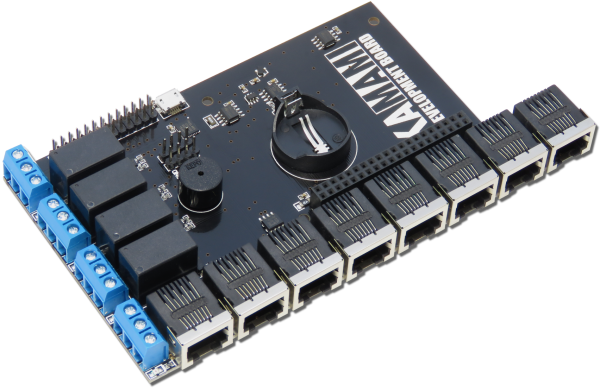
Nettemp Pi Hat is a module that allows to connect eight trees of sensors with I2C/1-Wire interface and control of four relays outputs. Thanks to the extension board is possible to build in an easy way e.g. multipunkt temperature controller.
Basic features and parameters
- Compatibility with NETTEMP software
- Extension board for Raspberry PI (version 3/2B/B+)
- Possibility of connection eight separate trees of sensors with I2C/1-Wire interface
- Module is supplied with minicomputer
- Embedded UART-USB converter (based on chip CP2102 from Silicon Labs)
- Embedded four relays with NO/NC outputs
- Load is connected by screw terminals
- Maximum load of relay pins: 3A / 250VAC
- Embedded real-time clock (M41T00S chip from STMicroelectronics)
- Embedded battery holder for RTC support
- Embedded buzzer
- Embedded connector allows to add a minicomputer without any wires
- Embedded pin connector GPIO 28-pin allows e.g. to add TFT display
- Mounting holes for Raspberry PI fastening
- Module size: 146mm x 80mm x 20mm
Standard equipment
| Code | Description |
|---|---|
| Nettemp Pi Hat |
|
Electrical schematic
View of PCB
Nettemp Pi Hat and Raspberry Pi
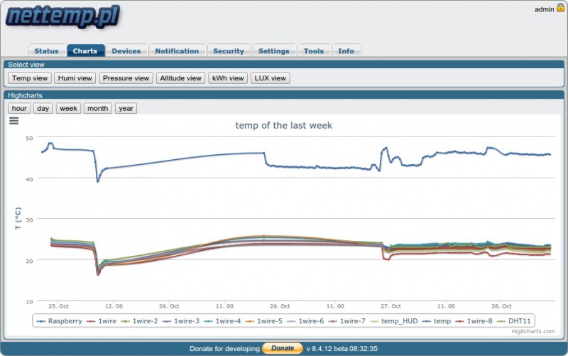
Nettemp – system of temperature monitor
Nettemp project started for monitor of temperature in flats of author to make a optimalization of rooms heating. Description of project, news and idea of project development can be find on site: www.nettemp.pl. Project assumptions included to provide a ready to use solution for wireless sensors management of temperature, humidity and light measurement and relays controll. Software part of project based on simple installer and WWW interface.
Simple use of Nettemp'a:
- Temperature, pressure and humidity measurement in server room
- Heat control at home
- Air conditioning control
- Sterowanie oświetleniem
On website www.nettemp.pl can you find a presentation film, fast installation script or list of compatibile sensors. Any problems or questions can you describe on forum on address: www.techfreak.pl/forum.
Relays outputs
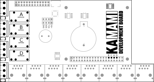
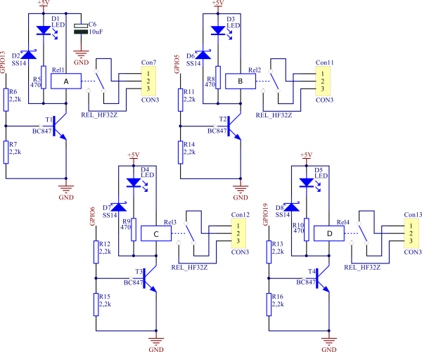
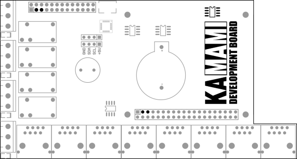
Nettemp Pi Hat board has an embedded four relays with control coils and LED controls of enabling. Module can be controlled via GPIO lines of Raspberry Pi (5, 6, 13,1 9 pins). Relays outputs are extended on screw terminals and are available normal close (NC) as well as normal open (NO) pins.
Sensors input with I2C / 1-Wire interface
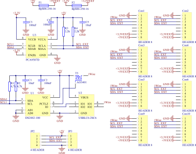
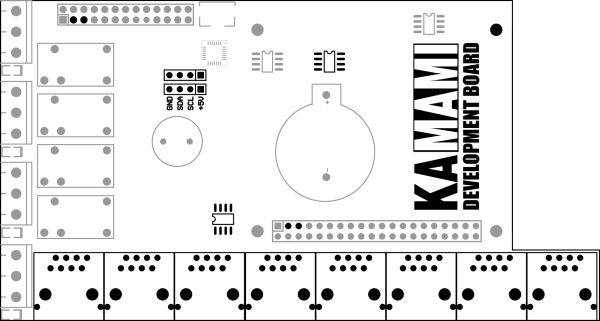
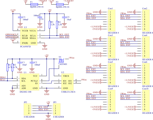
Embedded RJ-45 socket allow to connect sensors via I2C and 1-Wire interface (supplied via data line). Thanks to the eight sockets is possible to connect a lot of sensors by using separate wires with greater reliability of device. In I2C communication is used PCA9507 expander. It allows to increase a maximum range of work (to 18m). 1-Wire signals are converting to I2C signals by using Dallas DS2482 chip. Separatation between chip and sensors (connected to 1-Wire ports) is USBLC6-2SC6 chip. Signals of common I2C interface are connecting to the GPIO ports of Raspberry Pi (SCL to GPIO3 lines, SDA to GPIO2 line). In each RJ-45 port are following signals: 1-Wire, SCL (I2C), SDA (I2C), ground, 3V3 and 5V (both of power supply line are protected with polimer fuses with value 500mA). Maximum current available on power supply lines depends on possibility of Raspberry PI minicomputer. On board are also available to pin headers, I2C interface lines and 5V power supply (without fuse protection).
| Power supply lines of Raspberry Pi shouldn’t be overload. |
|---|
| SDA and SCL lines of I2C interface are pulled-up to 5V line. Before connection additional device, check compatibility of the device with this system. |
|---|
| RJ45 port pin | Function |
|---|---|
| 1 | Ground |
| 2 | 1-wire signal |
| 3 | SCL signal |
| 4 | SDA signal |
| 5 | NC |
| 6 | NC |
| 7 | Power supply +3,3 V |
| 8 | Power supply +5 V |
Embedded temperature sensor
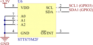
On board is placed a chip of temperature sensor STTS75M2F, connected with I2C interface to Raspberry Pi GPIO ports (SCL signal to GPIO3 line, SDA singal to GPIO2 line). Sensor allows to measure a temperature in range –55°C to +125°C.
UART – USB converter
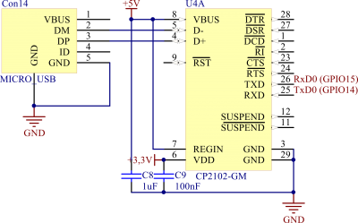
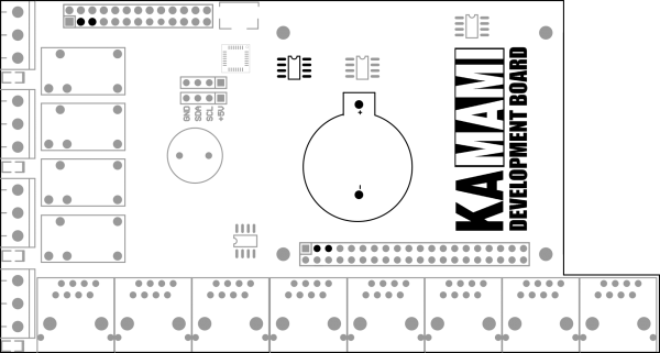
Embedded UART-USB converter allows to communicate of minicomputer with PC (e.g. via terminal). Converter uses a CP2102 chip and RxD and TxD line are connected to GPIO14 and GPIO15 line of Raspberry Pi (cross connection).
Real-time clock
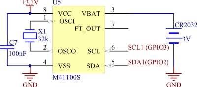
On Nettemp Pi Hat board is placed real-time clock (RTC) with battery holder for CR2032 battery (for support of RTC by losing of power supply). M41T00S chip has connected external oscillator with frequency 32.768kHz. Communication with chip is realized via I2C interface (SCL signal to GPIO3 line, SDA singal to GPIO2 line of Paspberry PI).
Buzzer
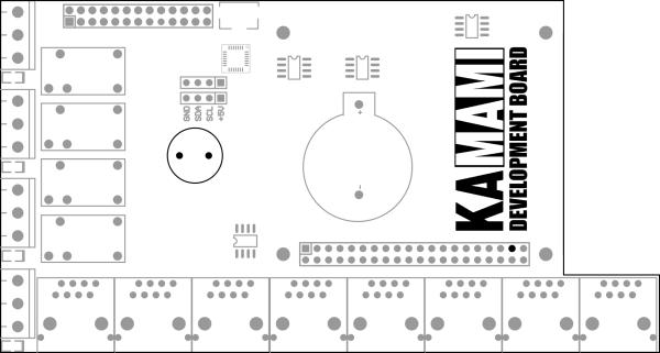
Embedded buzzer is conncted to GPIO26 line of Raspberry Pi. Converter hasn’t embedded generator. Thanks to that user has unlimited possibilities for sounds generation (included voice synthetization).
TFT display connector
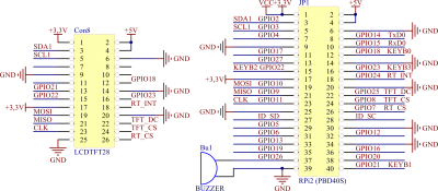
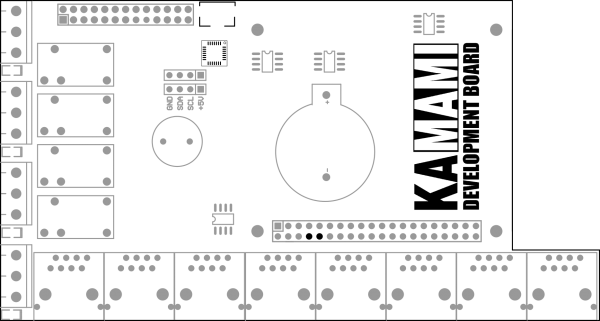
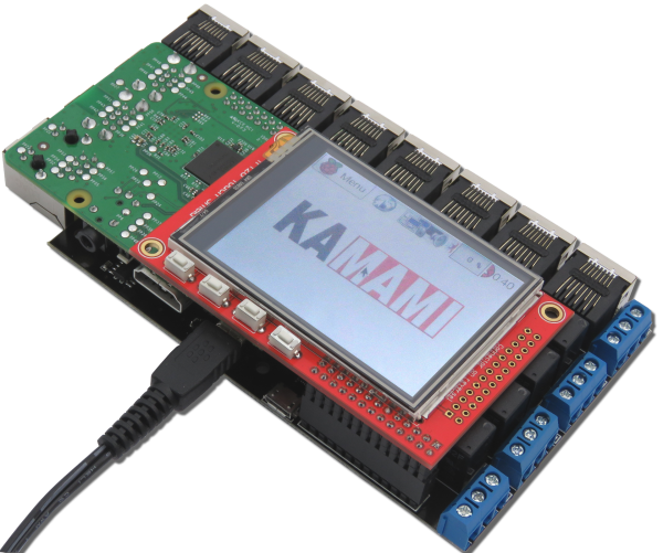
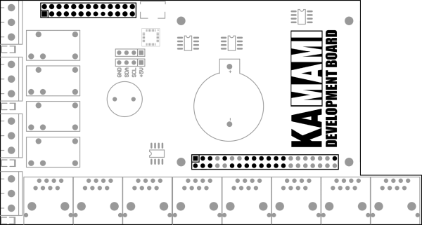
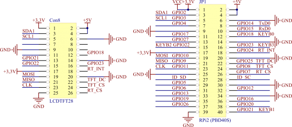
Double pins connector on board Nattemp Pi Hat allows to connect touch color display 2.8” with ILI9341 controller for Raspberry Pi (modRPi TFT28).
