ZL8AVR
From Kamamilabs.com - Wiki

Evaluation Board for dipAVR Mini-module
Introduction
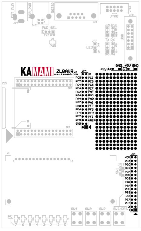
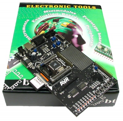
ZL8AVR is a versatile evaluation board designed for engineers and hobbyists who want to prototype systems based on AVR ATmega microcontrollers. ZL8AVR is prepared to operate with dipAVR mini-modules (ZL7AVR, ZL12AVR). Board's configuration is complete and user can find on the board the following components: USB interface connector (for ZL1USB module), RS232 interface with DB9F connector, simple keyboard (4 buttons), 8 LEDs, JTAG connector and socket for LCD display (2x16 characters). ZL8AVR board comes with examples of Bascom programs.
Features
- RS232 interface (with level converter and DB9F connector)
- JTAG connector
- Built-in 5 V voltage regulator
- Socket for LCD 2x16 character display (LCD1602 module)
- 8 LEDs
- MMC Flash card connector
- 4 microswitches
- Socket for USB interface (ZL1USB module)
- Prototype design area
- USB (5 V) or external (9...12 VDC) power supply
Contents of the package
| Code | Description |
|---|---|
| ZL8AVR |
|
Complete schematic
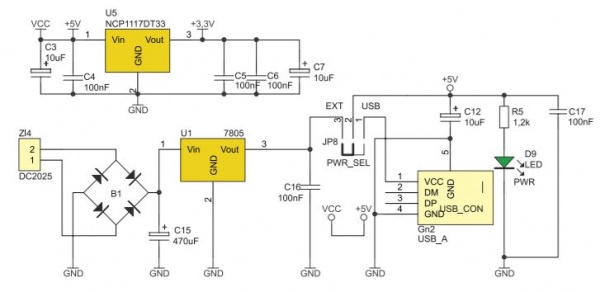
Circuit diagram is shown on Fig. 1. Recommended supply voltage is 9 VDC (9...12 VDC) connected via standard power jack or USB_PWR connector (selectable by JP8). Polarisation of input voltage is not important – bridge rectifier guarantees proper board operation in both cases.
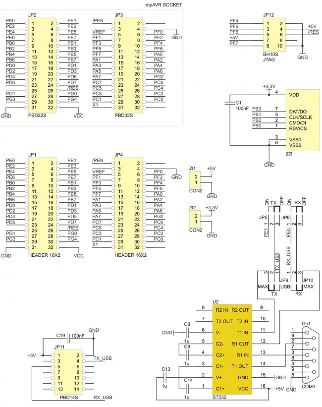
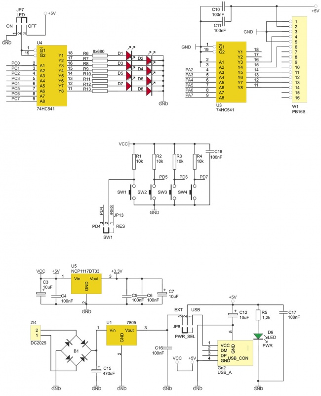
Fig. 1. Complete electric schematic of ZL8AVR board
dipAVR module
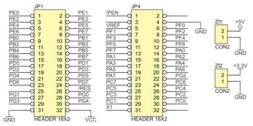
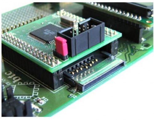
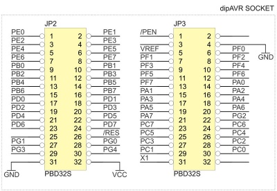
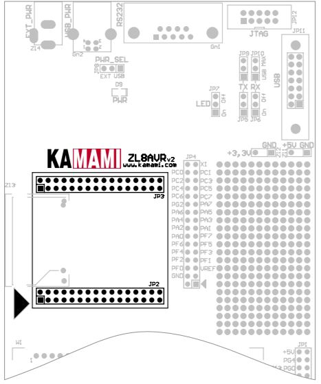
JP2 and JP3 connectors make socket for dipAVT module with AVR microcontroller.
ZL7AVR - dipAVR module with ATmega128 microcontroller:
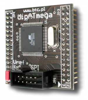
dipAVR module and ZL8AVR base board:
Power supply
ZL8AVR can be powered from:
- power supply adaptor (9...12 VDC/VAC, 250 mA),
- USB port.
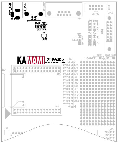
Power supply source selection (jumper JP8 – PWR_SEL)
| JP8 position | EXT (2-3) | USB (1-2) |
|---|---|---|
| Power supply source | ...EXT_PWR (ZL4) | ...USB_PWR (Gn2) |
Keyboard
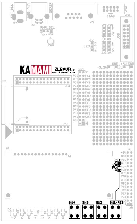
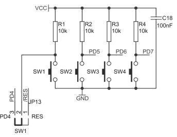
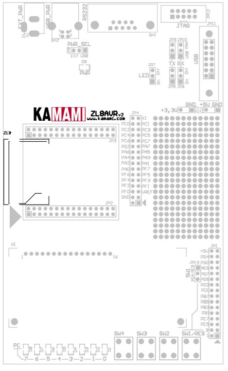
ZL8AVR has 4 switches. SW2...4 are connected to microcontroller port lines as shown in table. SW1 can be used as universal button or reset button (you can set its function by setting JP13 jumper)
Buttons to microcontroller line assingment
| AVR I/O line | PD7 | PD6 | PD5 | PD4 | RES |
|---|---|---|---|---|---|
| Switch | SW4 | SW3 | SW2 | SW1 (Set by JP13 ) | SW1 (Set by JP13 ) |
SW1 function
| AVR I/O line | PD4 | RES |
|---|---|---|
| JP13 position | PD4 | RES |
LEDs
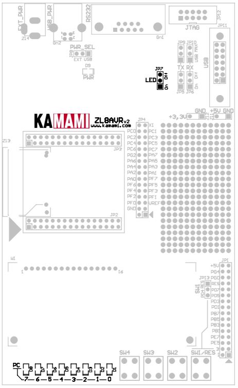
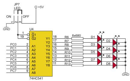
ZL8AVR is equipped with 8 LEDs, that show states of port PC lines. Jumper JP7 lets you turn on/off LEDs .
JP7 (LED) settings
| Position | Description |
|---|---|
| On (1-2) | LEDs D1...D8 show PC0...7 states |
| Off (2-3) | LEDs D1...D8 disconnected |
Connections between port PC lines and LEDs
| AVR I/O line | PC7 | PC6 | PC5 | PC4 | PC3 | PC2 | PC1 | PC0 |
|---|---|---|---|---|---|---|---|---|
| LED | D8 | D7 | D6 | D5 | D4 | D3 | D2 | D1 |
Alphanumeric LCD display
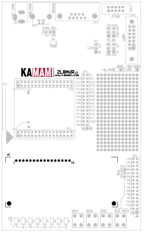
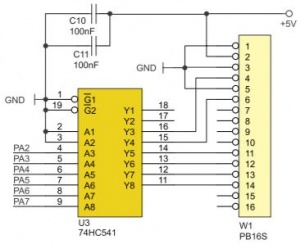
Standard LCD display with HD44780 controller (LCD1602 module) can be mounted in W1 socket.
Connections between microcontroller and display module
| AVR I/O line | PA2 | PA3 | PA4 | PA5 | PA6 | PA7 |
|---|---|---|---|---|---|---|
| LCD module signal name | RS | E | D4 | D5 | D6 | D7 |
| LCD module pin | 4 | 6 | 11 | 12 | 13 | 14 |
IRS232 and USB interfaces
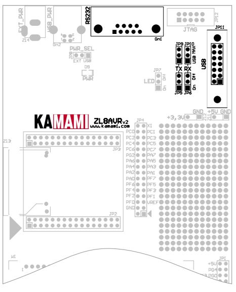
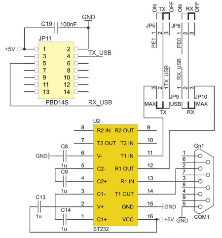
ZL8AVR has two serial communication interfaces:
- Built-in RS232 interface (voltage converter U2),
- USB interface (eg. ZL1USB), optionally connected to JP11 header.
Depending on selected communication interface, lines PE0 and PE1 have to be configured by jumpers
Communication interface selectors (other jumpers configurations are not allowed)
| Active port | JP5 | JP6 | JP9 | JP10 |
|---|---|---|---|---|
| USB | On | On | USB | USB |
| RS232 | On | On | MAX | MAX |
| None | Off | Off | - | - |
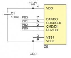
MMC card connector
ZL8AVR is equipped with MMC card connector. You can use cards with I/O interfaces that operate with at least 3.3 V voltage.
Connections between microcontroller and MMC card
| AVR I/O line | PB0 | PB1 | PB2 | PB3 |
|---|---|---|---|---|
| AVR signal name | /SS | SCK | MOSI | MISO |
| MMC card line | /CS | CLK | DataIn | DataOut |
JTAG connector
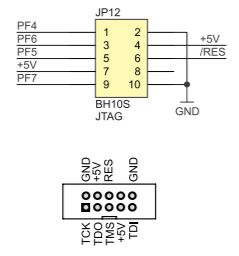
ZL8AVR is equipped with JP12 connector, that allows you to connect JTAG interface. Pin layout is compatible with Atmel JTAG standard
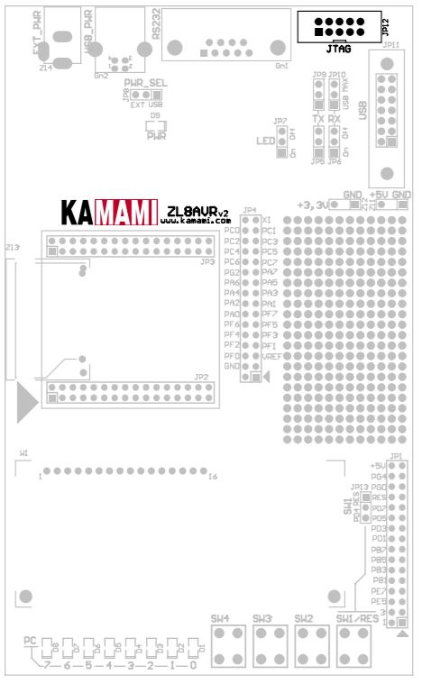
I/O headers
