KAmodLM75A: Difference between revisions
From Kamamilabs.com - Wiki
Created page with "__jzpdf__ ====== Opis ====== [https://kamami.pl/kamod-kamami/… KAmodLM75A] to moduł z czujnikiem temperatury LM75A firmy NXP. Płytka wyposażona została w złącze standa..." |
Anna Kubacka (talk | contribs) No edit summary |
||
| (4 intermediate revisions by one other user not shown) | |||
| Line 1: | Line 1: | ||
__jzpdf__ | __jzpdf__ | ||
====== | ====== Description ====== | ||
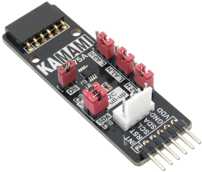
[https://kamami.pl/ | [https://kamami.pl/czujniki-temperatury/572188-kamodlm75a-modul-z-czujnikiem-temperatury.html KAmodLM75A] is a module with NXP LM75A temperature sensor. The board is equipped with a Pmod I2C standard connector and a KAMAMI connector, allowing easy attachment of the module to development kits. Due to its small dimensions, the product can be used in many development projects, while the Pmod through connector allows the boards to be connected in series. | ||
<center> | <center> | ||
[[File:KAmodLM75A_modul.png|none|400px|thumb|center]] | [[File:KAmodLM75A_modul.png|none|400px|thumb|center]] | ||
</center> | </center> | ||
===== | ===== Basic features ===== | ||
* | * LM75A chip from NXP | ||
** | ** I2C bus interface with up to 8 devices on the same bus (address configuration via jumpers) | ||
** | ** Temperature measurement in the range from -55 °C to +125 °C | ||
**11- | ** 11-bit ADC with a resolution of 0.125 °C | ||
** | ** Temperature measurement accuracy: | ||
***± 2 ° C | *** ± 2 ° C from -25 °C to +100 °C | ||
***± 3 ° C | *** ± 3 ° C from -55 °C to +125 °C | ||
** | ** Programmable temperature thresholds and hysteresis setpoints | ||
** | ** 3.5 µA power supply in off mode to save power | ||
** | ** Independent work as a thermostat when switching on | ||
** | ** Protection against electrostatic discharge | ||
* | * Through connector compatible with the Pmod standard, allows for serial connection of Pmod I2C modules | ||
* | * Connector compatible with the KAMAMI standard | ||
* | * Embedded jumpers enabling pull-up on I2C bus lines | ||
* | * Supply range from 2.8 V to 5.5 V | ||
* | * Mounting holes with a diameter of 2.5 mm | ||
* | * Dimensions: 61.2 mm x 20.3 mm x 10 mm | ||
===== | ===== Standard equipment ===== | ||
<center> | <center> | ||
{| class="wikitable" style="width: 1000px;" | {| class="wikitable" style="width: 1000px;" | ||
|- | |- | ||
! style="text-align: center;"| | ! style="text-align: center;"|Code | ||
! style="text-align: center;"| | ! style="text-align: center;"|Description | ||
|- | |- | ||
| style="text-align: center;"|<b>KAmodLM75A</b> | | style="text-align: center;"|<b>KAmodLM75A</b> | ||
| style="text-align: center;"| | | style="text-align: center;"| | ||
* | *Assembled and launched module | ||
|} | |} | ||
</center> | </center> | ||
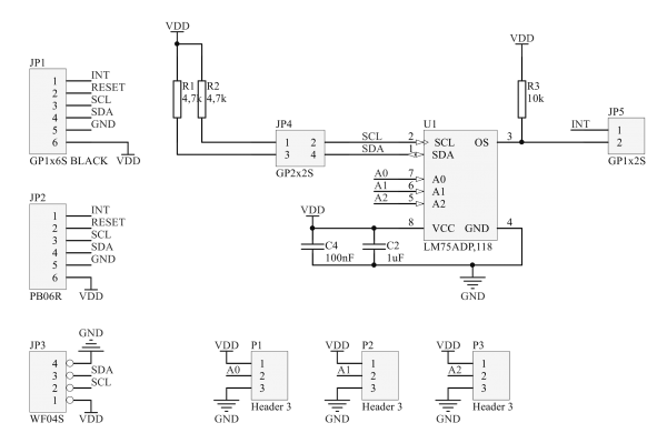
===== | ===== Schematic ===== | ||
<center> | <center> | ||
[[File:KAmodLM75A_schemat.png|none|600px|thumb|center]] | [[File:KAmodLM75A_schemat.png|none|600px|thumb|center]] | ||
</center> | </center> | ||
===== | ===== Output description - Pmod standard connector ===== | ||
<center> | <center> | ||
| Line 50: | Line 50: | ||
|- | |- | ||
! style="text-align: center;" rowspan="10"| [[File:KAmodLM75A_obrys_zlacze.png|center|150px]] | ! style="text-align: center;" rowspan="10"| [[File:KAmodLM75A_obrys_zlacze.png|center|150px]] | ||
! style="text-align: center;"|JP1 ( | ! style="text-align: center;"|JP1 (male connector) | ||
! style="text-align: center;"|JP2 ( | ! style="text-align: center;"|JP2 (female connector) | ||
! style="text-align: center;"| | ! style="text-align: center;"|Function | ||
|- | |- | ||
| style="text-align: center;"|VDD | | style="text-align: center;"|VDD | ||
| style="text-align: center;"|VDD | | style="text-align: center;"|VDD | ||
| rowspan="2" style="text-align: center;" | | | rowspan="2" style="text-align: center;" |Power supply of module (max. 5.5 V) | ||
|- | |- | ||
| style="text-align: center;"|GND | | style="text-align: center;"|GND | ||
| Line 63: | Line 63: | ||
| style="text-align: center;"|SDA | | style="text-align: center;"|SDA | ||
| style="text-align: center;"|SDA | | style="text-align: center;"|SDA | ||
| style="text-align: center;"| | | style="text-align: center;"|Data line of I2C bus | ||
|- | |- | ||
| style="text-align: center;"|SCL | | style="text-align: center;"|SCL | ||
| style="text-align: center;"|SCL | | style="text-align: center;"|SCL | ||
| style="text-align: center;"| | | style="text-align: center;"|Clock line of I2C bus | ||
|- | |- | ||
| style="text-align: center;"|RST | | style="text-align: center;"|RST | ||
| Line 75: | Line 75: | ||
| style="text-align: center;"|INT | | style="text-align: center;"|INT | ||
| style="text-align: center;"|INT | | style="text-align: center;"|INT | ||
| style="text-align: center;"| | | style="text-align: center;"|OS interrupt | ||
|} | |} | ||
</center> | </center> | ||
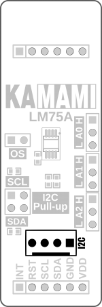
===== | ===== Output description – KAMAMI standard connector ===== | ||
<center> | <center> | ||
| Line 85: | Line 85: | ||
|- | |- | ||
! style="text-align: center;" rowspan="10"| [[File:KAmodLM75A_obrys_zlacza_kamami.png|center|150px]] | ! style="text-align: center;" rowspan="10"| [[File:KAmodLM75A_obrys_zlacza_kamami.png|center|150px]] | ||
! style="text-align: center;"| | ! style="text-align: center;"|Pin number | ||
! style="text-align: center;"| | ! style="text-align: center;"|Function | ||
|- | |- | ||
| style="text-align: center;"|1 (VDD_5V) | | style="text-align: center;"|1 (VDD_5V) | ||
| style="text-align: center;" | | | style="text-align: center;" |Power supply of module (max. 5,5 V) | ||
|- | |- | ||
| style="text-align: center;"|2 (SCL) | | style="text-align: center;"|2 (SCL) | ||
| style="text-align: center;"| | | style="text-align: center;"|Clock line of I2C bus | ||
|- | |- | ||
| style="text-align: center;"|3 (SDA) | | style="text-align: center;"|3 (SDA) | ||
| style="text-align: center;"| | | style="text-align: center;"|Data line of I2C bus | ||
|- | |- | ||
| style="text-align: center;"|4 (GND) | | style="text-align: center;"|4 (GND) | ||
| style="text-align: center;"| | | style="text-align: center;"| Ground | ||
|} | |} | ||
</center> | </center> | ||
====== | ====== I2C bus lines ====== | ||
The KAmodLM75A module is equipped with jumpers enabling the connection of pull-up resistors to the VCC power pole to the I2C bus line. The jumpers give the possibility of independent enabled of the pull-up for the SDA and SCL lines. | |||
<center> | <center> | ||
[[File:KAmodLM75A_obrys_i2c.png|none|200px|thumb|center]] | [[File:KAmodLM75A_obrys_i2c.png|none|200px|thumb|center]] | ||
</center> | </center> | ||
====== | ====== OS interrupt line ====== | ||
The KAmodLM75A module is equipped with a jumper to connect the OS interrupt output line (Overtemperature Shutdown) to the connector compatible with the Pmod standard. Thanks to the ability to disconnect the KAmodLM75A interrupt line from the Pmod connectors, the user does not have to worry about the consequences of any conflicts arising from connecting modules compatible with Pmod with different logic states. | |||
The OS output is for thermal interruption. After switching on the device, the output is only activated first if the temperature exceeds the limit temperature. The state remains active until it is reset by reading the register. | |||
<center> | <center> | ||
[[File:KAmodLM75A_obrys_os.png|none|200px|thumb|center]] | [[File:KAmodLM75A_obrys_os.png|none|200px|thumb|center]] | ||
</center> | </center> | ||
====== | ====== Configuration of the I2C bus address ====== | ||
The KAmodLM75A module has the option of configuring the I2C bus address in the range from 0x48 to 0x4F. Configuration of the address is done by means of three jumpers located on the module board. | |||
<center> | <center> | ||
[[File:KAmodLM75A_adres_i2c.png|none|200px|thumb|center]] | [[File:KAmodLM75A_adres_i2c.png|none|200px|thumb|center]] | ||
</center> | </center> | ||
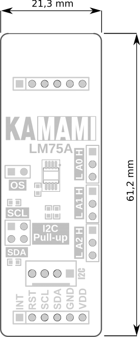
===== | ===== Dimensions ===== | ||
<center> | <center> | ||
[[File:KAmodLM75A_wymiary_PCB.png|none|275px|thumb|center]] | [[File:KAmodLM75A_wymiary_PCB.png|none|275px|thumb|center]] | ||
</center> | </center> | ||
===== | ===== External links ===== | ||
*[ | *[https://download.kamami.pl/p572188-LM75A%20datasheet.pdf LM75A datasheet] | ||
Latest revision as of 07:56, 23 September 2020

Description
KAmodLM75A is a module with NXP LM75A temperature sensor. The board is equipped with a Pmod I2C standard connector and a KAMAMI connector, allowing easy attachment of the module to development kits. Due to its small dimensions, the product can be used in many development projects, while the Pmod through connector allows the boards to be connected in series.
Basic features
- LM75A chip from NXP
- I2C bus interface with up to 8 devices on the same bus (address configuration via jumpers)
- Temperature measurement in the range from -55 °C to +125 °C
- 11-bit ADC with a resolution of 0.125 °C
- Temperature measurement accuracy:
- ± 2 ° C from -25 °C to +100 °C
- ± 3 ° C from -55 °C to +125 °C
- Programmable temperature thresholds and hysteresis setpoints
- 3.5 µA power supply in off mode to save power
- Independent work as a thermostat when switching on
- Protection against electrostatic discharge
- Through connector compatible with the Pmod standard, allows for serial connection of Pmod I2C modules
- Connector compatible with the KAMAMI standard
- Embedded jumpers enabling pull-up on I2C bus lines
- Supply range from 2.8 V to 5.5 V
- Mounting holes with a diameter of 2.5 mm
- Dimensions: 61.2 mm x 20.3 mm x 10 mm
Standard equipment
| Code | Description |
|---|---|
| KAmodLM75A |
|
Schematic
Output description - Pmod standard connector
 |
JP1 (male connector) | JP2 (female connector) | Function |
|---|---|---|---|
| VDD | VDD | Power supply of module (max. 5.5 V) | |
| GND | GND | ||
| SDA | SDA | Data line of I2C bus | |
| SCL | SCL | Clock line of I2C bus | |
| RST | RST | - | |
| INT | INT | OS interrupt |
Output description – KAMAMI standard connector
 |
Pin number | Function |
|---|---|---|
| 1 (VDD_5V) | Power supply of module (max. 5,5 V) | |
| 2 (SCL) | Clock line of I2C bus | |
| 3 (SDA) | Data line of I2C bus | |
| 4 (GND) | Ground |
I2C bus lines
The KAmodLM75A module is equipped with jumpers enabling the connection of pull-up resistors to the VCC power pole to the I2C bus line. The jumpers give the possibility of independent enabled of the pull-up for the SDA and SCL lines.

OS interrupt line
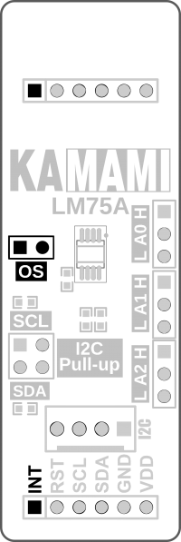
The KAmodLM75A module is equipped with a jumper to connect the OS interrupt output line (Overtemperature Shutdown) to the connector compatible with the Pmod standard. Thanks to the ability to disconnect the KAmodLM75A interrupt line from the Pmod connectors, the user does not have to worry about the consequences of any conflicts arising from connecting modules compatible with Pmod with different logic states. The OS output is for thermal interruption. After switching on the device, the output is only activated first if the temperature exceeds the limit temperature. The state remains active until it is reset by reading the register.
Configuration of the I2C bus address
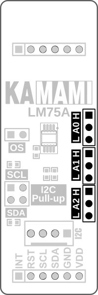
The KAmodLM75A module has the option of configuring the I2C bus address in the range from 0x48 to 0x4F. Configuration of the address is done by means of three jumpers located on the module board.
Dimensions
