KAmodM41T82: Difference between revisions
From Kamamilabs.com - Wiki
Created page with "__jzpdf__ ====== Opis ====== [https://kamami.pl/kamod-kamami/… KAmodM41T82] to moduł z zegarem RTC M41T82 firmy STMicroelectronics. Płytka wyposażona została w złącze..." |
Anna Kubacka (talk | contribs) No edit summary |
||
| (4 intermediate revisions by one other user not shown) | |||
| Line 1: | Line 1: | ||
__jzpdf__ | __jzpdf__ | ||
====== | ====== Description ====== | ||
[https://kamami.pl/ | [https://kamami.pl/en/rtc-modules/575708-kamodm41t82-a-module-with-rtc-clock.html KAmodM41T82] is a module with with the STMicroelectronics M41T82 RTC clock. The board is equipped with a Pmod I2C standard connector and a KAMAMI connector, that allows easy connection of the module to the evaluation kits. Due to its small dimensions, the product can be used in many development projects, while the Pmod loop connector allows to connect the boards in the series. | ||
<center> | <center> | ||
[[File:KAmodM41T82_modul.png|none| | [[File:KAmodM41T82_modul.png|none|500px|thumb|center]] | ||
</center> | </center> | ||
===== | ===== Basic features and parameters ===== | ||
* | * M41T82 chip from STMicroelectronics | ||
** | **Precise timing (tenth/hundredth of a second, seconds, minutes, hours, days, date, month, year and century) | ||
** | **Ultra-low battery supply current of 365 nA | ||
** | **Programmable 8-bit counter | ||
**7 | **7 bytes of SRAM memory with battery backup | ||
** | **Detection of the oscillator stop | ||
** | **I2C bus | ||
** | **Chip address 0xD0 | ||
* | * Connector compatible with the Pmod standard, allows serial connection of Pmod I2C modules | ||
* | * The connector complies with the KAMAMI standard | ||
* | * Embedded jumpers activating pull-up on I2C bus lines | ||
* | * Embedded jumper connecting the INT line of the chip to the INT line of Pmod connectors | ||
* | * Possibility to supply voltage from 1.95-3.5V | ||
* | * Mounting holes with a diameter of 2.5mm | ||
* | * Dimensions: 61.2mm x 20.3mm x 10mm | ||
===== | ===== Standard equipment ===== | ||
<center> | <center> | ||
{| class="wikitable" style="width: 1000px;" | {| class="wikitable" style="width: 1000px;" | ||
|- | |- | ||
! style="text-align: center;"| | ! style="text-align: center;"|Code | ||
! style="text-align: center;"| | ! style="text-align: center;"|Description | ||
|- | |- | ||
| style="text-align: center;"|<b>KAmodM41T82</b> | | style="text-align: center;"|<b>KAmodM41T82</b> | ||
| style="text-align: left;"| | | style="text-align: left;"| | ||
* | *Assembled and launched module | ||
|} | |} | ||
</center> | </center> | ||
===== | ===== Electrical schematics ===== | ||
<center> | <center> | ||
[[File:KAmodM41T82_schemat.png|none|600px|thumb|center]] | [[File:KAmodM41T82_schemat.png|none|600px|thumb|center]] | ||
</center> | </center> | ||
===== | ===== Output description - Pmod standard connector ===== | ||
<center> | <center> | ||
| Line 48: | Line 48: | ||
|- | |- | ||
! style="text-align: center;" rowspan="10"| [[File:KAmodM41T82_obrys_zlacze.png|center|150px]] | ! style="text-align: center;" rowspan="10"| [[File:KAmodM41T82_obrys_zlacze.png|center|150px]] | ||
! style="text-align: center;"|JP1 | ! style="text-align: center;"|JP1 male connector) | ||
! style="text-align: center;"|JP2 ( | ! style="text-align: center;"|JP2 (female connector) | ||
! style="text-align: center;"| | ! style="text-align: center;"|Function | ||
|- | |- | ||
| style="text-align: center;"|VDD | | style="text-align: center;"|VDD | ||
| style="text-align: center;"|VDD | | style="text-align: center;"|VDD | ||
| rowspan="2" style="text-align: center;" | | | rowspan="2" style="text-align: center;" | Power supply of module (max. 5.5V) | ||
|- | |- | ||
| style="text-align: center;"|GND | | style="text-align: center;"|GND | ||
| Line 61: | Line 61: | ||
| style="text-align: center;"|SDA | | style="text-align: center;"|SDA | ||
| style="text-align: center;"|SDA | | style="text-align: center;"|SDA | ||
| style="text-align: center;"| | | style="text-align: center;"|Data line of I2C bus | ||
|- | |- | ||
| style="text-align: center;"|SCL | | style="text-align: center;"|SCL | ||
| style="text-align: center;"|SCL | | style="text-align: center;"|SCL | ||
| style="text-align: center;"| | | style="text-align: center;"|Clock line of I2C bus | ||
|- | |- | ||
| style="text-align: center;"|RST | | style="text-align: center;"|RST | ||
| Line 73: | Line 73: | ||
| style="text-align: center;"|INT | | style="text-align: center;"|INT | ||
| style="text-align: center;"|INT | | style="text-align: center;"|INT | ||
| style="text-align: center;"| - | | style="text-align: center;"| - | ||
|} | |} | ||
</center> | </center> | ||
===== | ===== Output description – KAMAMI standard connector ===== | ||
<center> | <center> | ||
| Line 83: | Line 83: | ||
|- | |- | ||
! style="text-align: center;" rowspan="10"| [[File:KAmodM41T82_obrys_zlacza_kamami.png|center|150px]] | ! style="text-align: center;" rowspan="10"| [[File:KAmodM41T82_obrys_zlacza_kamami.png|center|150px]] | ||
! style="text-align: center;"| | ! style="text-align: center;"|Pin number | ||
! style="text-align: center;"| | ! style="text-align: center;"|Function | ||
|- | |- | ||
| style="text-align: center;"|1 (VDD_5V) | | style="text-align: center;"|1 (VDD_5V) | ||
| style="text-align: center;" | | | style="text-align: center;" | Power supply of module (max. 5,5 V) | ||
|- | |- | ||
| style="text-align: center;"|2 (SCL) | | style="text-align: center;"|2 (SCL) | ||
| style="text-align: center;"| | | style="text-align: center;"|Clock line of I2C bus | ||
|- | |- | ||
| style="text-align: center;"|3 (SDA) | | style="text-align: center;"|3 (SDA) | ||
| style="text-align: center;"| | | style="text-align: center;"|Data line of I2C bus | ||
|- | |- | ||
| style="text-align: center;"|4 (GND) | | style="text-align: center;"|4 (GND) | ||
| style="text-align: center;"| | | style="text-align: center;"| Ground | ||
|} | |} | ||
</center> | </center> | ||
====== I2C bus lines ====== | |||
====== | The KAmodMMA8653FC module is equipped with jumpers allowing to connect pull-up resistors to the positive power pole to the I2C bus line. The jumpers give the possibility of independent enabled of the pull-up for the SDA and SCL lines. | ||
<center> | <center> | ||
[[File:KAmodM41T82_obrys_i2c.png|none|200px|thumb|center]] | [[File:KAmodM41T82_obrys_i2c.png|none|200px|thumb|center]] | ||
</center> | </center> | ||
====== | ====== Battery connector ====== | ||
The KAmodM41T82 module has been equipped with a connector enabling the connection of a battery supporting the power supply in the event of a main power failure. Thanks to this, the module will not lose data regarding the time measured and will allow for uninterrupted work. A battery with a voltage between 2-5,5V may be connected to the connector. | |||
<center> | <center> | ||
[[File:KAmodM41T82_obrys_bat.png|none|200px|thumb|center]] | [[File:KAmodM41T82_obrys_bat.png|none|200px|thumb|center]] | ||
</center> | </center> | ||
===== | ===== Dimensions ===== | ||
<center> | <center> | ||
[[File:KAmodM41T82_wymiary_PCB.png|none|275px|thumb|center]] | [[File:KAmodM41T82_wymiary_PCB.png|none|275px|thumb|center]] | ||
</center> | </center> | ||
===== | ===== External links ===== | ||
*[ | *[https://download.kamami.pl/p575708-m41t82%20datasheet.pdf Datasheet of KAmodM41T82 chip from STMicroelectronics] | ||
Latest revision as of 09:02, 23 September 2020

Description
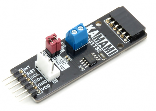
KAmodM41T82 is a module with with the STMicroelectronics M41T82 RTC clock. The board is equipped with a Pmod I2C standard connector and a KAMAMI connector, that allows easy connection of the module to the evaluation kits. Due to its small dimensions, the product can be used in many development projects, while the Pmod loop connector allows to connect the boards in the series.
Basic features and parameters
- M41T82 chip from STMicroelectronics
- Precise timing (tenth/hundredth of a second, seconds, minutes, hours, days, date, month, year and century)
- Ultra-low battery supply current of 365 nA
- Programmable 8-bit counter
- 7 bytes of SRAM memory with battery backup
- Detection of the oscillator stop
- I2C bus
- Chip address 0xD0
- Connector compatible with the Pmod standard, allows serial connection of Pmod I2C modules
- The connector complies with the KAMAMI standard
- Embedded jumpers activating pull-up on I2C bus lines
- Embedded jumper connecting the INT line of the chip to the INT line of Pmod connectors
- Possibility to supply voltage from 1.95-3.5V
- Mounting holes with a diameter of 2.5mm
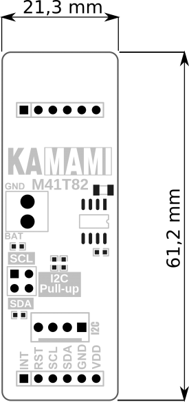
- Dimensions: 61.2mm x 20.3mm x 10mm
Standard equipment
| Code | Description |
|---|---|
| KAmodM41T82 |
|
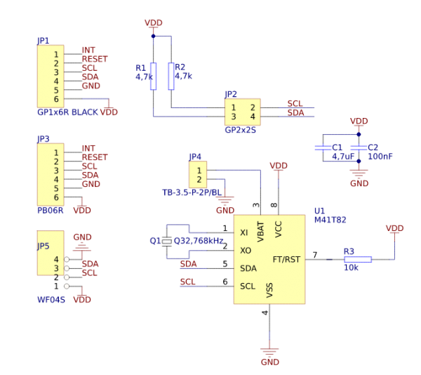
Electrical schematics
Output description - Pmod standard connector
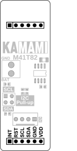 |
JP1 male connector) | JP2 (female connector) | Function |
|---|---|---|---|
| VDD | VDD | Power supply of module (max. 5.5V) | |
| GND | GND | ||
| SDA | SDA | Data line of I2C bus | |
| SCL | SCL | Clock line of I2C bus | |
| RST | RST | - | |
| INT | INT | - |
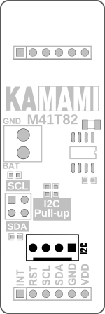
Output description – KAMAMI standard connector
 |
Pin number | Function |
|---|---|---|
| 1 (VDD_5V) | Power supply of module (max. 5,5 V) | |
| 2 (SCL) | Clock line of I2C bus | |
| 3 (SDA) | Data line of I2C bus | |
| 4 (GND) | Ground |
I2C bus lines
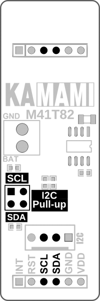
The KAmodMMA8653FC module is equipped with jumpers allowing to connect pull-up resistors to the positive power pole to the I2C bus line. The jumpers give the possibility of independent enabled of the pull-up for the SDA and SCL lines.
Battery connector
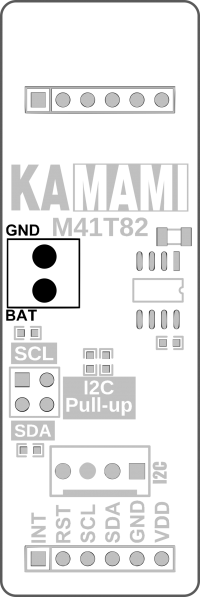
The KAmodM41T82 module has been equipped with a connector enabling the connection of a battery supporting the power supply in the event of a main power failure. Thanks to this, the module will not lose data regarding the time measured and will allow for uninterrupted work. A battery with a voltage between 2-5,5V may be connected to the connector.
Dimensions
