KAmodRPi CAN-FD: Difference between revisions
From Kamamilabs.com - Wiki
| (One intermediate revision by the same user not shown) | |||
| Line 1: | Line 1: | ||
__jzpdf__ | __jzpdf__ | ||
===== Description ===== | ===== Description ===== | ||
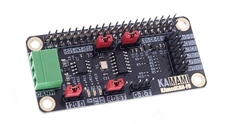
<b>KAmodRPi CAN-FD </b> is a complete CAN bus interface based on the advanced CAN controller type MCP2518FD. The system used is responsible for forming correct frames sent to the bus, and buffering data sent to and from the CAN bus. Thanks to these features, it can work with almost any SBC computer or microcontroller. Communication on the CAN side can take place at a speed of up to 1 Mbps in CAN 2.0 mode or up to 8 Mbps in CAN FD mode. Communication with the controller takes place via a 4-wire SPI interface (MISO, MOSI, SCK, CE) and an additional interrupt signal (INT). All signals are fed to a 40-pin connector so that 2 modules can work simultaneously with one Raspberry Pi 5 computer. | <b>[https://kamami.pl/en/communication-modules/1189248-kamodrpi-can-fd-can-interface-compatible-with-can-20-and-can-fd-for-raspberry-pi-and-more-5906623481477.html KAmodRPi CAN-FD] </b> is a complete CAN bus interface based on the advanced CAN controller type MCP2518FD. The system used is responsible for forming correct frames sent to the bus, and buffering data sent to and from the CAN bus. Thanks to these features, it can work with almost any SBC computer or microcontroller. Communication on the CAN side can take place at a speed of up to 1 Mbps in CAN 2.0 mode or up to 8 Mbps in CAN FD mode. Communication with the controller takes place via a 4-wire SPI interface (MISO, MOSI, SCK, CE) and an additional interrupt signal (INT). All signals are fed to a 40-pin connector so that 2 modules can work simultaneously with one Raspberry Pi 5 computer. | ||
<center> | <center> | ||
[[File:KAMOD_CAN_FD_1.jpg|none|900px|thumb|center]] | [[File:KAMOD_CAN_FD_1.jpg|none|900px|thumb|center]] | ||
| Line 83: | Line 83: | ||
| style="text-align: center;"|<b>J2</b> | | style="text-align: center;"|<b>J2</b> | ||
2x20 goldpin connector, 2.54 mm | 2x20 goldpin connector, 2.54 mm | ||
| style="text-align: left;"| * CAN controller control signals are connected to the appropriate GPIO connector pins | | style="text-align: left;"| | ||
* CAN controller control signals are connected to the appropriate GPIO connector pins | |||
* Power input is connected to the appropriate GPIO connector pins | * Power input is connected to the appropriate GPIO connector pins | ||
|} | |} | ||
Latest revision as of 16:02, 26 October 2024

Description
KAmodRPi CAN-FD is a complete CAN bus interface based on the advanced CAN controller type MCP2518FD. The system used is responsible for forming correct frames sent to the bus, and buffering data sent to and from the CAN bus. Thanks to these features, it can work with almost any SBC computer or microcontroller. Communication on the CAN side can take place at a speed of up to 1 Mbps in CAN 2.0 mode or up to 8 Mbps in CAN FD mode. Communication with the controller takes place via a 4-wire SPI interface (MISO, MOSI, SCK, CE) and an additional interrupt signal (INT). All signals are fed to a 40-pin connector so that 2 modules can work simultaneously with one Raspberry Pi 5 computer.
Basic parameters
- CAN bus interface, compatible with CAN 2.0 and CAN FD
- Based on the MCP2518FD CAN controller
- Communication via SPI interface with a maximum clock speed of 20 MHz
- SPI interface operating at 3.3 V or 5 V
- Communication speed (bit rate): 125 kbps...1 Mbps (500 kbps...8 Mbps in FD mode)
- Attachable 120 Ω terminating resistor
- LEDs indicating correct power supply and communication
- Compatible with Raspberry boards Pi 5 and others from the Raspberry Pi family
- Possibility to connect two modules to one computer (communication via one SPI interface with separate CE0/CE1 lines)
- CAN bus lines connected via Phoenix MC 3.81 mm connector
- Protection against overvoltages on CAN bus lines
- Power supply 5 V, 100 mA
- Board dimensions 65x30 mm, height approx. 25 mm
Standard equipment
| Code | Description |
|---|---|
| KAmod CAN-FD | Assembled and started module |
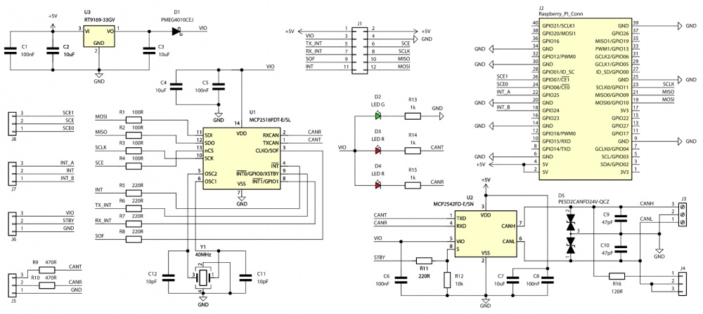
Wiring diagram
Control connector
| Connector | Function |
|---|---|
| J1
Goldpin pins 1x6, 2.54 mm |
|
The MCP2518FD CAN controller is controlled via the SPI interface. SPI is used to configure operating parameters and transfer data to and from the controller. Additionally, the controller provides several additional signals - interrupts, which allow for quick response to specific events. All lines operate with a voltage of 3.3 V, but can optionally be configured to operate with a voltage of 5 V.
The functions of the signals on the J1 connector are as follows:
- pins no. 1 and 2: +5V - power input with a voltage of 4.5...5.5 V;
- pin no. 3: VIO - optional power input for a voltage of 3.3...5 V, if the control signals are to operate with a voltage higher than 3.3 V;
- pin no. 4: GND - power and signal ground;
- pin no. 5: TINT – TX Interrupt output, active low;
- pin no. 6: CE – SPI chip select input, active low;
- pin no. 7: RINT – RX Interrupt output, active low;
- pin no. 8: SCK – SPI clock input of the CAN controller;
- pin no. 9: SOF – Start of Frame output;
- pin no. 10: MISO – SPI data output of the CAN controller;
- pin no. 11: INT – main interrupt output, active low;
- pin no. 12: MOSI – CAN controller SPI data input;
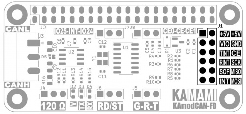
GPIO connector in Raspberry Pi standard
| Connector | Function |
|---|---|
| J2
2x20 goldpin connector, 2.54 mm |
|
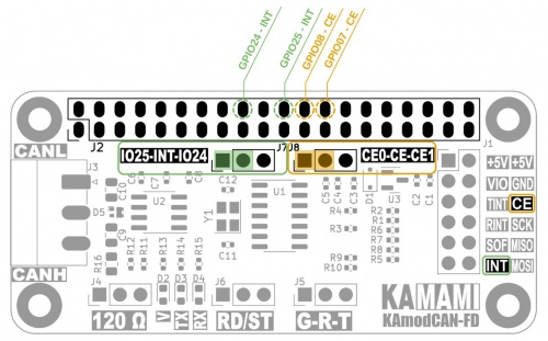
The CAN controller control signals are connected to the appropriate pins of the J2 connector (and in parallel to the J1 connector), which is compatible with the GPIO connector standard of the Raspberry Pi boards. Thanks to this, the KAmod CAN-FD module can be easily connected to the Raspberry Pi SBC. The arrangement of the control signals on the GPIO connector is as follows:
- position no. 2 marked "3V3" - shorting pins 3-4 means that the serial control interface is adapted to the voltage of 3.3 V, which is suppliede from the integrated voltage regulator on the board;
- pins 2 and 4: +5V – 5V power supplied from the GPIO connector;
- pins 6, 9, 14, 20, 25, 30, 34, 39 – ground GND supplied from the GPIO connector;
- pin 18: GPIO24 – can be connected to the INT signal (depending on the J7 jumper setting);
- pin 22: GPIO25 – can be connected to the INT signal (depending on the J7 jumper setting);
- pin 24: GPIO08 – can be connected to the CE signal (depending on the J8 jumper setting);
- pin 26: GPIO07 – can be connected to the CE signal (depending on the J8 jumper setting);
- pin 19: GPIO10 – connected to the MOSI signal - CAN controller SPI data input;
- pin 19: GPIO09 – connected to the MISO signal - CAN controller SPI data output;
- pin 19: GPIO11 – connected to the SCK signal - CAN controller SPI clock input;
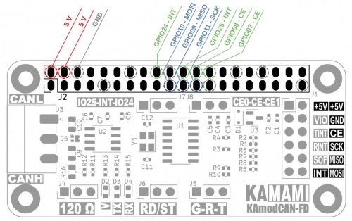
Connecting two CAN interface modules
| Connector | Function |
|---|---|
| J7, J8
Goldpin + jumper 1x3, 2.54 mm |
|
The KAmod CAN-FD module is controlled via the SPI serial interface, which can support several controllers in one application. Each controller should have a CE (Chip Enable) selection line assigned to it. There are two CE lines available on the Raspberry Pi GPIO connector - CE0 and CE1. Using the J8 jumper, you can select which CE line the CAN controller on the KAmod CAN-FD module board will use:
- shorting pins 1-2 J8: sets the CE0 line as the controller selection line (as shown),
- shorting pins 2-3 J8: sets the CE1 line as the controller selection line.
The MCP2518FD CAN controller requires an interrupt to be set by the state on the INT line to work properly. To enable the operation of two CAN controllers, the INT signal can be connected to one of the two GPIO connector pins, using the J7 jumper:
- shorting pins 1-2 J7: the INT signal is connected to the GPIO25 line (as shown),
- shorting pins 2-3 J7: the INT signal is connected to the GPIO24 line.
CAN bus connector
| Connector | Function |
|---|---|
| J3 - CAN
Phoenix MC 3.81 mm |
|
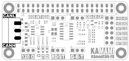
The CAN bus connector has 3 pins: CANL, CANH and GND. Their arrangement is described on the module board, the GND contact is the middle contact. Each contact should be connected to the CAN bus according to the marking. The GND signal should be connected to the common ground of the power supply of devices connected by the CAN bus.
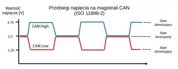
The voltage waveforms on the CAN bus are shown in the figure below:
Connecting the terminating resistor
| Connector | Function |
|---|---|
| J4
Goldpin + jumper 1x3, 2.54 mm |
|
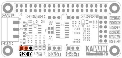
Devices in the CAN bus, as the name suggests, are connected in a bus topology. This is a single bus, without branches, in which two ends can be indicated. Each end of the bus should be equipped with a bus terminator - in the case of the CAN bus, this is a resistor with a value of 120 Ω. There is a suitable resistor on the module board, which can be connected by setting the J4 jumper appropriately:
- shorting pins 1-2 means that the 120 Ω terminating resistor is connected between the CANL and CANH lines (as shown);
- shorting pins 2-3 or removing the jumper disconnects the terminating resistor.
CAN bus transceiver off
| Connector | Function |
|---|---|
| J6
Goldpin + jumper 1x3, 2.54 mm |
|
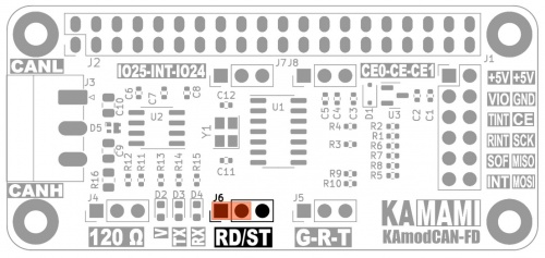
During CAN communication tests and trials, it may be necessary to cut off access to the bus so that the tested application does not interfere with the communication of other devices. The KAmod CAN-FD module contains a MCP25 type transceiver42FD, which adapts the data stream from the CAN controller to the electrical parameters of the bus. A quick way to cut off access to the bus, without modifying the wiring, is to turn off the transceiver - setting the standby sleep mode. Using the J6 pins, you can easily turn the transceiver on/off:
- shorting pins 1-2: transceiver active (as shown in the figure),
- shorting pins 2-3: transceiver in standby sleep mode.
Monitoring TX and RX data streams
| Connector | Function |
|---|---|
| J5
Goldpin + jumper 1x3, 2.54 mm |
|
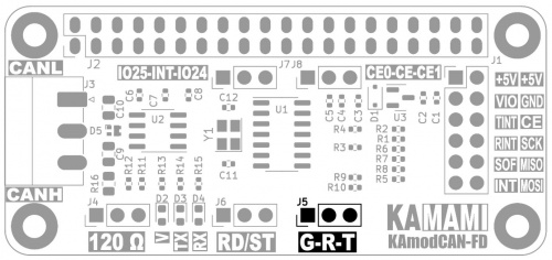
The J5 connector of the KAmod CAN-FD module outputs data stream signals sent from the controller and to the CAN controller. These are ordinary logical signals, so they can be easily monitored and recorded, for example, using a logic analyzer. The voltage level of the signals corresponds to the VIO voltage. Monitoring these signals can be useful at the stage of starting the application and finding errors. The signal layout is as follows:
- pin no. 1: G – signal ground,
- pin no. 2: R – data stream received from the CAN bus,
- pin no. 3: T – data stream sent to the CAN bus from the controller.
VIO control signal power supply and voltage
| Connector | Function |
|---|---|
| J1
2x6 goldpin pins, 2.54 mm |
|
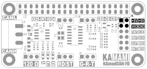
The CAN transceiver (MCP2542FD) used in the KAmod CAN-FD module requires a power supply with a voltage in the range of 4.5...5.5 V, which should be connected to the J1 connector, to the +5V and GND contacts. On the other hand, the power supply of the CAN controller (MCP2518FD) may be lower - it must be in the range of 3...5.5 V. The voltage of the control signals on the J1 connector will be the same as the controller's power supply voltage.
The CAN controller is powered by a voltage of 3.3 V from the voltage regulator built into the module. This voltage is output on the VIO contact of the J1 connector. By applying a voltage higher than 3 V, e.g. 5 V, to the VIO pin, you can obtain a higher voltage of the control signals – e.g. 5V.
The functions of the power pins on the J1 connector are as follows:
- pins 1 and 2: +5V - power input with a voltage of 4.5...5.5 V;
- pin 3: VIO – optional power input for a voltage of 3.3...5 V, if the control signals are to operate with a voltage higher than 3.3 V;
- pin 4: GND – power and signal ground;
Indicator diodes
| Type | Function |
|---|---|
| RX TX V |
|
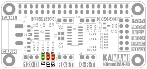
The RX and TX LEDs indicate the active state – i.e. low logical state (dominant state on the CAN bus), respectively at the output and input of the CAN transceiver. In the case of data transmission to the bus, both LEDs will flash – TX and RX, because the data is simultaneously read by the transceiver. The V LED indicates the presence of CAN controller voltage.
Dimensions
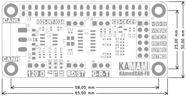
The dimensions of the KAmod CAN-FD interface module are 65x30 mm, and the height is about 25 mm. The module is compatible with Raspberry Pi 5 and Raspberry Pi Zero boards.
Links
- MCP2518 datasheet
- MCP2542FD datasheet
- Article on the MIKROKONTROLER.pl portal "CAN communication interface: basics"
- Linux CAN tool repository
Running the module with Raspberry Pi 5
Running the CAN interface with Raspberry Pi 5 requires the following steps.
Unblocking the SPI interface
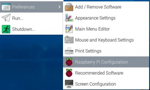
Run the Raspberry Pi configuration program - Raspberry Pi Configuration
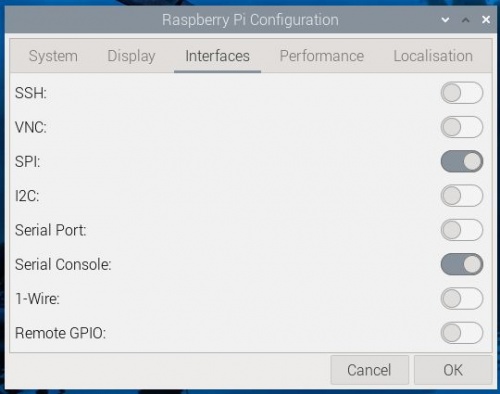
Select the Interfaces tab, and there switch the switch to the active positionk at SPI. Save and close the program.
Installing the CAN interface toolkit
Run a terminal window, e.g. using the Ctrl+Alt+T keys, and then enter the command:
sudo apt-get install can-utils
Wait until it finishes and confirm all queries.
Configuring the CAN interface
We launch a terminal window, e.g. using the Ctrl+Alt+T keys. In the nano text file editor, open the config.txt file by entering the command:
sudo nano /boot/firmware/config.txt
(in earlier versions of the Raspbian system, the config.txt file is here: /boot/config.txt)
We check whether the line with the content:
dtparam=spi=on
does not have the # sign; if so, remove the # sign
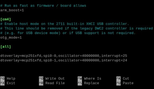
At the end of the file, we add:
dtoverlay=mcp251xfd,spi0-0,oscillator=40000000,interrupt=25
This entry refers to the jumper setting on the module board (J7: 1-2; J8: 1-2)
If we intend to connect two CAN interface modules, we should add another line:
dtoverlay=mcp251xfd,spi0-1,oscillator=40000000,interrupt=24
This entry refers to the jumper setting on the module board (J7: 2-3; J8: 2-3)
Save changes by pressing Ctrl+O and confirm with Enter, then close the editor by pressing Ctrl+X
Restarting the system
Restart the system, e.g. using the command:
sudo reboot
Checking the configuration
Run a terminal window, e.g. using the keys Ctrl+Alt+T. Enter the command:
dmesg | grep spi
which will display information about the SPI interface collected during system startup:

If everything has been configured correctly, we should see two entries (or one if only one module is installed): mcp251xfd spi0.0 and mcp251xfd spi0.1. which means that the CAN controllers have been successfully initialized - successfully initialized.
Now you need to enter the command:
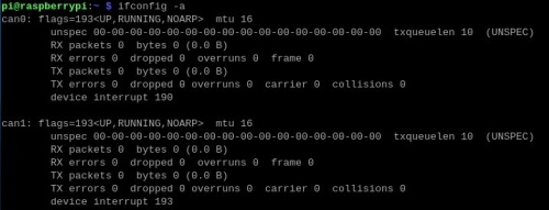
ifconfig -a
which will display a list of available network interfaces - Ethernet, Wi-Fi and CAN:
Communication test
The simplest communication test can be performed with two KAmod CAN-FD CAN interface modules connected to one Raspberry Pi 5 computer. However, the test will be performed similarly with two computers equipped with the KAmod CAN-FD interface.
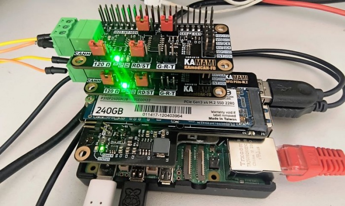
We launch the terminal window, e.g. using the keys Ctrl+Alt+T. We activate the CAN bus with the command:
sudo ip link set can0 up type can bitrate 1000000
where:
can0 - is the interface number, for the second module it will be can1
bitrate 1000000 - means the communication speed, in this case we set 1 Mbps
For the second module, enter a similar command:
sudo ip link set can1 up type can bitrate 1000000
Now we open the second terminal - in one window we will observe the data received via one CAN interface (e.g. can0), and in the second window we will send data frames via the second CAN interface (e.g. can1). In the first window we enter the command:
candump can0
which makes the can0 interface display all received data in the terminal.
In the second window, enter the command:
cansend can1 456#214234
The effect can be seen in the screenshots below:


The command cansend can1 456#214234 causes a CAN frame with identifier 456 to be sent with 3 bytes of data: 21, 42, and 34. In the CAN 2.0B standard, the identifier is 29 bits long, and the frame can contain up to 8 bytes of data. The command candump can0 monitors the bus status and displays all received data frames. To interrupt this process, press Ctrl+C.
To change communication parameters, first deactivate the CAN bus using the commands
sudo ifconfig can0 down
sudo ifconfig can1 down
Testcommunication in CAN FD mode
The CAN2.0 standard allows you to send up to 8 bytes of data at a speed of up to 1 Mbps. The CAN FD (Controller Area Network Flexible Data-Rate) standard allows you to send up to 64 bytes of data in one frame, by increasing the communication speed inside the frame - during data transfer, to 8 Mbps:

The KAmod CAN-FD module is compatible with the CAN FD standard. To test the module in this mode, perform the following steps.
We start the terminal window, e.g. using the Ctrl+Alt+T keys. We activate the CAN bus with the command:
sudo ip link set can0 up type can bitrate 1000000 dbitrate 8000000 restart-ms 1000 berr-reporting on fd on
We proceed similarly with the second bus:
sudo ip link set can1 up type can bitrate 1000000 dbitrate 8000000 restart-ms 1000 berr-reporting on fd on
Now we will use a tool to generate random CAN frames – cangen. In the first terminal window, enter the command:
cangen can0 -mv
In the second terminal window, enter the command:
candump can1
The effect is visible in the screenshot below:

Among the generated frames, you can see those that carry no data, only the identifier itself, and those that carry 20 bytes of data - in accordance with the capabilities of CAN FD.