FREEboard: Difference between revisions
From Kamamilabs.com - Wiki
Anna Kubacka (talk | contribs) Created page with "__jzpdf__ ===== Description ===== FREEboard is a richly equipped development board with microcontroller from family Freescale KINETIS L (core ARM Cortex-M0+ @48 MHz), compatib..." |
No edit summary |
||
| (One intermediate revision by one other user not shown) | |||
| Line 1: | Line 1: | ||
__jzpdf__ | __jzpdf__ | ||
===== Description ===== | ====== Description ====== | ||
FREEboard is a richly equipped development board with microcontroller from family Freescale KINETIS L (core ARM Cortex-M0+ @48 MHz), compatible with Arduino R3 and evaluation boards Freescale FREEDOM (FRDM). | FREEboard is a richly equipped development board with microcontroller from family Freescale KINETIS L (core ARM Cortex-M0+ @48 MHz), compatible with Arduino R3 and evaluation boards Freescale FREEDOM (FRDM). | ||
| Line 6: | Line 6: | ||
[[File:freeboard_prawie_z_gory.JPG|none|400px|thumb|center]] | [[File:freeboard_prawie_z_gory.JPG|none|400px|thumb|center]] | ||
</center> | </center> | ||
===== Basic parameters ===== | ===== Basic parameters ===== | ||
Latest revision as of 16:04, 1 November 2024

Description
FREEboard is a richly equipped development board with microcontroller from family Freescale KINETIS L (core ARM Cortex-M0+ @48 MHz), compatible with Arduino R3 and evaluation boards Freescale FREEDOM (FRDM).
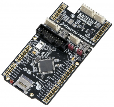
Basic parameters
- Two boards: base with microcontroller and expander 7DoF
- Microcontroller MKL25Z128VLK
- Core Cortex-M0+, clocked up to 48 MHz
- Memory Flash/SRAM: 128 kB/16 kB
- Sensors MEMS 7DoF: MAG3110, MPL3115, MMA8451
- MicroSD slot card
- LED RGB + 2xLED
- USB2.0
- 54 lines GPIO (LV-TTL – 3,3 V)
- Microswitch
- I2C and SPI connectors in Kamod system
- JTAG/SWD connector (standard J-Link, uLink itp.)
- Power supply from USB or external power supply 3,5...6 VDC
- Jumper for current consumption measurement
| Additional materials, datasheets and software examples are available on site |
Standard equipment
| Code | Description |
|---|---|
| FREEboard |
|
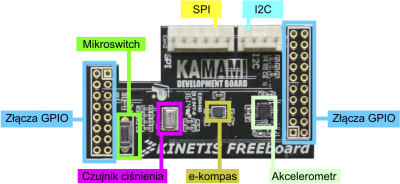
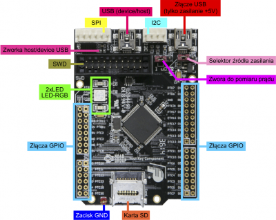
Placement of boards components
Electrical schematic of base board
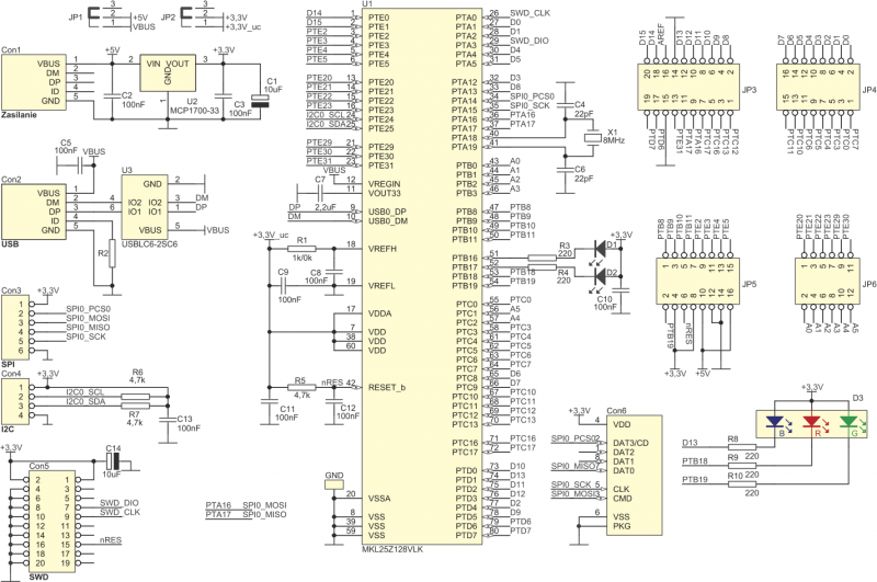
LED and LED-RGB connection to microcontroller
LEDs are connected to GPIO lines of microcontroller in this way that are enable when on output is logical “0”.
| GPIO lines | Diode |
|---|---|
| PTB16 | D! |
| PTB17 | D2 |
| PTB18 | D3-RED |
| PTB19 | D3-GREEN |
| PTD1 | D3-BLUE |
GPIO lines of microcontroller
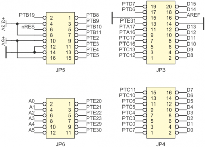
GPIO lines are available on goldpin connector as on picture below. Placement of GPIO lines as well as power supply lines (GND, +3,3 V and +5 V) on connector is compatible with Arduino R3 standard.
| Some GPIO lines are available only on additional SPI (Con3) and I2C (Con4) connector, also D1 (PTB16) i D2 (PTB17) are controlled from output lines, which aren’t available on goldpin connector. |
| Some GPIO line (as e.g. PTA16 and PTA17) are available on goldpin connector are at the same time used for SPI communication. When SPI communication is used, availability of this lines necessary for communication should be verify. |
SPI Connector
GPIO lines of SPI0 interface of microcontroller are connected to Con4 connector and to microSD card slot Con6.
| PTA16 and PTA17 lines are used as universal GPIO lines! |
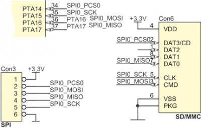
| SPI0 lines | GPIO of microcontroller | Comments |
|---|---|---|
| CS | PTA14 | - |
| SCK | PTA15 | - |
| MOSI | PTA16 | Available as PTA16 on JP3 connector |
| MISO | PTA17 | Available as PTA17 on JP3 connector |
I2C connector
I2C0 interface lines are available on Con4 connector. Both lines are pulled up to power supply (+3,3 VDC) with resistors R6 i R7.

| I2C0 line | GPIO of microcontroller |
|---|---|
| SCL | PTE24 |
| SDA | PTE25 |
USB connector
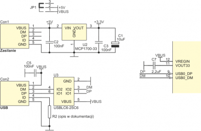
FREEboard is equipped with two USB connectors (Con1 i Con2), with which one (Con1) is used only for power supplying of board (+5 VDC), second (Con2) is connected to lines DM and DP of microcontroller USB interface. USB interface in microcontroller MKL25Z128VLK can work in host or device mode. Depending on the selected mode of operation R2 (0W) should be:
- mounted on board (host),
- not mounted on board (device, default configuration).
In the case of working as a host, jumper JP1 should be placed on pins 1-2, which will provide +5 VDC power to the cooperating device.
Debugger/programmer SWD connector
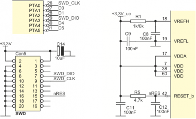
FREEboard is equipped with w 20-pins IDC connector, which make possible to program and debug of microcontroller with SWD interface via JTAG/SWD typically connector.
| Due to the price and possibilities, we recommend using the J-Link EDU programmer-debugger. |
MicroSD card slot
MicroSD card slot in board FREEboard is connected to SPI0 interface. Details are described in part „SPI connector”.
Configuration jumpers
In the case of USB microcontroller interface operation as a host, JP1 jumper should be placed on pins 1-2, which will provide +5 VDC power to the cooperating device. In the case of working in device mode, the jumper JP1 should have shorted contacts 2-3 or the jumper should be removed from the contacts JP1. The JP2 jumper make possible to convenient measurement of the current consumption of the microcontroller - it is placed in series with the microcontroller VDD and VDDA power lines. The correct operation of the microcontroller from the board is possible if:
- jumper connect pins 1-2 of JP2 jumper or
- jumper is removed from JP2 and between pins 1-2 JP2 is connected ammeter with a small internal resistance.
JP1 functions
| Closed contacts | Function |
|---|---|
| 1-2 | Power supply +5 V (z Con1) connected to VBUS line (required in USB host). Optional: if its is needed to power the board with USB Con2. |
| 2-3 | Power supply of board from Con1, position recommended in USB device mode. |
| Jumper removed | As in the case when contacts are closed 2-3. |
JP2 functions
| Closed contacts | Function |
|---|---|
| 1-2 | Normal power supply |
| 2-3 | Power supply of microcontroller off |
| Jumper removed | After connecting ammeters to pins 1 and 2, you can measure the current used by the microcontroller. |
Power supply
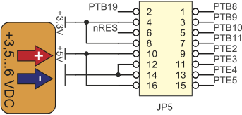
The USB Con1 connector is provided for supplying the board. If necessary, the supply voltage can also be connected to pins 10 or 16 JP5 (acceptable range 3,5...6 VDC).
| Incorrectly inserted jumper on JP2 can can prevent the microcontroller from working (more details in part "Configuration jumpers")! |
Expander 7DoF
The standard element of the FREEboard set is the expander board with sensors MEMS 7DoF (compass 3D – U1, accelerometer 3D – U3 and pressure sensor – U2). Electrical schematic of the expander is shown in the picture below.
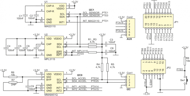
R7 resistor (not mounted) allows to change the address of the accelerometer U3 on I2C interface, its installation requires removing of R6 (int this case state on SA0 changes from „1” on „0”). All MEMS sensors for communication with the microcontroller use I2C interfaces. Compass sensor and pressure sensor are connected to the I2C1 interface, and the accelerometer requires connection to I2C0 via wires (SDA and SCL lines on Con1 expander and Con4 connectors on the FREEboard). If all the possibilities of the expander board will be used, it is necessary to make another two connections using wires. It should connect Con2 pins of expander with Con3 of FREEboard. The recommended way to connect the 7DoF expander to a FREEboard is shown in the table below.
| Connector/pin of expander 7DoF | Connector/pin of FREEboard | Function | Busy line GPIO/dedicated | Connection realized |
|---|---|---|---|---|
| Con1/1 | Con4/1 | +3,3 VDC (power supply) | - | External wire, e.g. CAB_HU04-30 |
| Con1/2 | Con4/2 | SCL of accelerometer | PTE24 | External wire, e.g. CAB_HU04-30 |
| Con1/3 | Con4/3 | SDA of accelerometer | PTE25 | External wire, e.g. CAB_HU04-30 |
| Con1/4 | Con4/4 | GND (power supply) | - | External wire, e.g. CAB_HU04-30 |
| Con2/2 | Con3/2 | INT1 of accelerometer | PTA14 | External wire, e.g. CAB_HU06-30 or CAB_F-F |
| Con2/5 | Con3/5 | INT2 of accelerometer | PTA15 | External wire, e.g. CAB_HU06-30 or CAB_F-F |
| JP1/20 | JP3/20 | SCL of magnetometer and pressure sensor | PTE1 | By setting up an expander on FREEboard |
| JP1/18 | JP3/18 | SDA magnetometer and pressure sensor | PTE0 | By setting up an expander on FREEboard |
| JP1/12 | JP3/12 | INT of magnetometer | PTD! | By setting up an expander on FREEboard |
| JP1/10 | JP3/10 | INT of pressure sensor | PTD3 | By setting up an expander on FREEboard |
| JP2/15 | JP3/15 | Microswitch Sw1 | PTE5 | By setting up an expander on FREEboard |