KA-LOGO!-IO-Simulator: Difference between revisions
From Kamamilabs.com - Wiki
No edit summary Tag: Manual revert |
|||
| (23 intermediate revisions by 4 users not shown) | |||
| Line 1: | Line 1: | ||
====== | __jzpdf__ | ||
[https://kamami.pl/sterowniki-plc/563006-ka-logo-io-simulator-zestaw-symulacyjny-dla-sterownika-siemens-logo-8.html KA-LOGO!-IO-Simulator] to | ====== Description ====== | ||
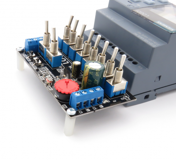
[https://kamami.pl/sterowniki-plc/563006-ka-logo-io-simulator-zestaw-symulacyjny-dla-sterownika-siemens-logo-8.html KA-LOGO!-IO-Simulator] kit helps to simulate logical states on the [https://kamami.pl/sterowniki-plc/563424-zestaw-startowy-logo-8-siemens-rce-6ed1052-1md00-0ba8.html Siemens LOGO! 8] logical controler. With the IO simulator board, You can simulate each bits on the LOGO! inputs using toggle switches. It is possible to use the embedded LOGO! ADC's to measure a voltage, ALS or temperature values. | |||
<center> | <center> | ||
[[ | [[File:KA-LOGO!-IO-Simulator_modul.png|none|600px|thumb|center]] | ||
</center> | </center> | ||
Included LED module can signalise states of four LOGO! outputs. Integrated LED drivers (NCR401U by Nexperia) provides constant brightness of the indicators. | |||
<center> | <center> | ||
[[ | [[File:KA-LOGO!-IO-Simulator_modul_LED.png|none|500px|thumb|center]] | ||
</center> | </center> | ||
The kit is especially recommended for Automation Engineers and persons, who wants to learn and tests their codes without connecting every used sensors. | |||
<center> | <center> | ||
{| class="wikitable" style="width: 1000px;" | {| class="wikitable" style="width: 1000px;" | ||
|- | |- | ||
! style="text-align: center;"| | ! style="text-align: center;"|Attention! The product is designed for the Siemens 6ED1052-1MD00-0BA8 and 6ED1052-1MD08-0BA0 logic controllers. In case of using the product with other Siemens Logo! 8 controller, please ensure it's compatibility. | ||
|} | |} | ||
</center> | </center> | ||
===== Parameters ===== | |||
*IO simulator module: | |||
**The module is dedicated for using with LOGO! 8 (supplied from 24 V DC) | |||
**It has gold plated pins, which provides the best contact with PLC terminal blocks. | |||
**It allows to simulate each eight bits using two position switches | |||
**It allows to use the capabilities of the built-in LOGO! 8 ADC converters by measure the analog value from sensors (switch by J7, J8): | |||
***temperature sensor MCP9700, with output voltage scalled to the measure range of LOGO! 8 (+5…+105°C) | |||
***potentiometer | |||
***phototoresistor (ALS) | |||
***external sensor, connected to the terminal blocks (EXTIN) | |||
**It is equipped with terminal blocks, which gives the possibility of easy connecting to the 24V DC power source and to the external sensor. | |||
**Using special spacers (included), the IO simulator module doesn't strain the terminal blocks of LOGO! 8 logic controller. | |||
<center> | <center> | ||
{| class="wikitable" style="width: 1000px;" | {| class="wikitable" style="width: 1000px;" | ||
|- | |- | ||
! style="text-align: center;"| | ! style="text-align: center;"|Attention! The IO simulator module works correctly only with LOGO! 8 supplied from the 24V DC power source. | ||
|} | |} | ||
</center> | </center> | ||
*LED indicators module: | |||
**The module is dedicated for using with LOGO! 8 (supplied from 24 V DC) | |||
**Gives a posibility of indicating digital output states of the LOGO! 8 (Q1...Q4) | |||
**Built-in NCR401U LED drivers by Nexperia provides constant lights brightness | |||
**It has gold plated pins, which provides the best contact with PLC terminal blocks. | |||
**It has terminal block, which gives the possibility of easy connecting the 24V DC lines | |||
<center> | <center> | ||
{| class="wikitable" style="width: 1000px;" | {| class="wikitable" style="width: 1000px;" | ||
|- | |- | ||
! style="text-align: center;"| | ! style="text-align: center;"|Attention! LED indicators module works correctly only with the LOGO! 8 supplied from the 24V DC power source. | ||
! | |||
|} | |} | ||
</center> | </center> | ||
===== | ===== Included ===== | ||
<center> | <center> | ||
{| class="wikitable" style="width: 1000px;" | |||
|- | |||
! style="text-align: center;"|Code | |||
! style="text-align: center;"|Description | |||
|- | |||
| style="text-align: center;"|<b>KA-LOGO!-IO-Simulator</b> | |||
| style="text-align: left;"| | |||
*Assembled and tested module of IO simulator | |||
*Assembled and tested module of LED indicators | |||
*Two spacer sleeves | |||
*Two screws for spacer sleeves | |||
|} | |||
</center> | </center> | ||
===== | ===== Terminal blocks (for supply) ===== | ||
The IO simulator module has four terminal blocks. Connectors marked as "L+" and "M" are used to connecting and forwarding the power supply between modules. Double terminal blocks on the left side allows for: | |||
*[upper] - connect a power supply to the module and the LOGO! 8 device | |||
*[lower] - forward supply for the IO indicators module | |||
<center> | <center> | ||
[[ | [[File:KA-LOGO!-IO-Simulator_zlacza_srubowe.png|none|500px|thumb|center]] | ||
</center> | </center> | ||
===== | ===== Simulator's board switches ===== | ||
The IO simulator module is equipped with toggle switches marked as INP: I1-I8, , which sets the digital states on each lines of the LOGO! 8 module. Selectors INP: I7, I8 can be used to connect the analog signals to LOGO! 8 ADC's. Using two switches "SEL", You can configure the signal character on the I7/I8 lines (by connecting to supply voltages for bit simulation or by connecting to a analog lines). | |||
Slide switches allows to configure the analog inputs. Line Al1 might be connected to ALS sensor (LIGHT) or potentiometer (POT). For the Al2 line You can select readings from temperature sensor (TEMP) or external analog input (EXTIN). | |||
<center> | <center> | ||
{| class="wikitable" style="width: 1000px;" | {| class="wikitable" style="width: 1000px;" | ||
|- | |- | ||
! style="text-align: center;"| | ! style="text-align: center;"|Switch | ||
! style="text-align: center;"| | ! style="text-align: center;"|Position | ||
! style="text-align: center;"|Description | |||
|- | |||
| rowspan="2" style=" text-align: center; "|I1...I8 | |||
| style="text-align: center;"|0 | |||
| style="text-align: center;"|Low logic level on the I1...I8 lines | |||
|- | |||
| style="text-align: center;"|1 | |||
| style="text-align: center;"|High logic level on the I1...I8 lines | |||
|- | |||
| rowspan="2" style=" text-align: center; "|SEL [I7/Al1] | |||
| style="text-align: center;"|I7 | |||
| style="text-align: center;"|I7 switch sets the logical states | |||
|- | |||
| style="text-align: center;"|Al1 | |||
| style="text-align: center;"|The I7 voltage depends on the analog value from ALS sensor or potentiometer | |||
|- | |||
| rowspan="2" style=" text-align: center; "|SEL [I8/Al2] | |||
| style="text-align: center;"|I8 | |||
| style="text-align: center;"|I8 switch sets the logical states | |||
|- | |||
| style="text-align: center;"|Al2 | |||
| style="text-align: center;"|The I8 voltage depends on the analog value from temperature sensor or the EXTIN input | |||
|- | |- | ||
| style="text-align: center;"| | | rowspan="2" style=" text-align: center; "|LIGHT/POT | ||
| style="text-align: center;"| | | style="text-align: center;"|LIGHT | ||
| style="text-align: center;"|Analog voltage measures from the ALS sensor | |||
|- | |||
| style="text-align: center;"|POT | |||
| style="text-align: center;"|Analog voltage measures from the potentiometer slide. | |||
|- | |||
| rowspan="2" style=" text-align: center; "|TEMP/EXTIN | |||
| style="text-align: center;"|TEMP | |||
| style="text-align: center;"|Analog voltage measures from the temperature sensor | |||
|- | |||
| style="text-align: center;"|EXTIN | |||
| style="text-align: center;"|Analog voltage measures from the EXTIN input | |||
|} | |} | ||
</center> | </center> | ||
===== | ===== Potentiometer ===== | ||
The potentiometer on the IO simulator board could be connected to the I7 line. Voltage of the potentiometer slide has range from 0 to 10 Volts DC. | |||
===== Ambient Light Sensor ===== | |||
The ALS sensor of the IO Simulation board could be connected to the I7 line of LOGO! 8. Output voltage of the photoresitor has range from 0 to 10 Volts DC (depending on ambient light level). | |||
===== Temperature sensor ===== | |||
On the IO Simulator module the voltage matching circut is applied for temperature sensor MCP9700. It scales the temperature sensor output voltage to the ADC range of LOGO! 8 device. | |||
On the line I8, it is possible to obtain 0 to 10 V DC range (with 12-20mV margin from 10V line) for temperatures measured from +5 to +105 Centigrade degrees. | |||
===== External sensor connector (EXTIN) ===== | |||
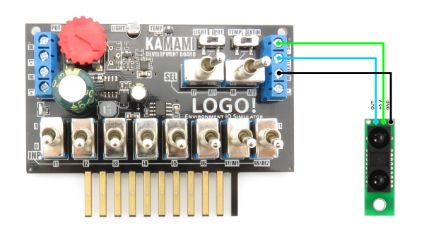
It is possible to connect a external sensor to the IO Simulator module. Output voltage of connected sensor must not be higher than 5V DC. 5V power supply for the external sensor is available on terminal block, located at right side. | |||
For example, the compatible external sensor is [https://kamami.pl/odleglosci/560840-sharp-gp2y0a60szlf-analogowy-czujnik-odleglosci-10-150cm-5v.html Pololu - 2474]. Connection method is shown on the image: | |||
<center> | <center> | ||
[[ | [[File:KA-LOGO!-IO-Simulator_zlacze_extin.png|none|600px|thumb|center]] | ||
</center> | </center> | ||
===== | ===== Spacer sleeves ===== | ||
Included spacer sleeves needs to be mounted to the IO Simulator module for preventing a tensions of board (and the excessive exploitation of LOGO! 8 terminal blocks). The mountage method is shown on the foto: | |||
<center> | |||
[[File:KA-LOGO!-IO-Simulator_tuleje_dystansowe.png|none|600px|thumb|center]] | |||
</center> | |||
[ | ===== External links ===== | ||
*[http://ep.com.pl/artykuly/11565-Przykladowa_aplikacja_LOGO_Cyfrowy_termometr_z_sygnalizacja_przekroczenia_progow.html Article (language: PL) "Sample application of LOGO! 8. Digital thermometer with signaling of over thresholds" on the EP portal] | |||
Latest revision as of 16:05, 1 November 2024

Description
KA-LOGO!-IO-Simulator kit helps to simulate logical states on the Siemens LOGO! 8 logical controler. With the IO simulator board, You can simulate each bits on the LOGO! inputs using toggle switches. It is possible to use the embedded LOGO! ADC's to measure a voltage, ALS or temperature values.
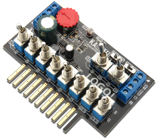
Included LED module can signalise states of four LOGO! outputs. Integrated LED drivers (NCR401U by Nexperia) provides constant brightness of the indicators.
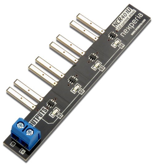
The kit is especially recommended for Automation Engineers and persons, who wants to learn and tests their codes without connecting every used sensors.
| Attention! The product is designed for the Siemens 6ED1052-1MD00-0BA8 and 6ED1052-1MD08-0BA0 logic controllers. In case of using the product with other Siemens Logo! 8 controller, please ensure it's compatibility. |
|---|
Parameters
- IO simulator module:
- The module is dedicated for using with LOGO! 8 (supplied from 24 V DC)
- It has gold plated pins, which provides the best contact with PLC terminal blocks.
- It allows to simulate each eight bits using two position switches
- It allows to use the capabilities of the built-in LOGO! 8 ADC converters by measure the analog value from sensors (switch by J7, J8):
- temperature sensor MCP9700, with output voltage scalled to the measure range of LOGO! 8 (+5…+105°C)
- potentiometer
- phototoresistor (ALS)
- external sensor, connected to the terminal blocks (EXTIN)
- It is equipped with terminal blocks, which gives the possibility of easy connecting to the 24V DC power source and to the external sensor.
- Using special spacers (included), the IO simulator module doesn't strain the terminal blocks of LOGO! 8 logic controller.
| Attention! The IO simulator module works correctly only with LOGO! 8 supplied from the 24V DC power source. |
|---|
- LED indicators module:
- The module is dedicated for using with LOGO! 8 (supplied from 24 V DC)
- Gives a posibility of indicating digital output states of the LOGO! 8 (Q1...Q4)
- Built-in NCR401U LED drivers by Nexperia provides constant lights brightness
- It has gold plated pins, which provides the best contact with PLC terminal blocks.
- It has terminal block, which gives the possibility of easy connecting the 24V DC lines
| Attention! LED indicators module works correctly only with the LOGO! 8 supplied from the 24V DC power source. |
|---|
Included
| Code | Description |
|---|---|
| KA-LOGO!-IO-Simulator |
|
Terminal blocks (for supply)
The IO simulator module has four terminal blocks. Connectors marked as "L+" and "M" are used to connecting and forwarding the power supply between modules. Double terminal blocks on the left side allows for:
- [upper] - connect a power supply to the module and the LOGO! 8 device
- [lower] - forward supply for the IO indicators module
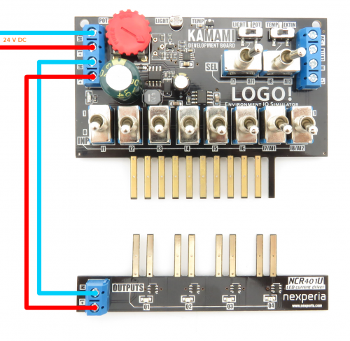
Simulator's board switches
The IO simulator module is equipped with toggle switches marked as INP: I1-I8, , which sets the digital states on each lines of the LOGO! 8 module. Selectors INP: I7, I8 can be used to connect the analog signals to LOGO! 8 ADC's. Using two switches "SEL", You can configure the signal character on the I7/I8 lines (by connecting to supply voltages for bit simulation or by connecting to a analog lines). Slide switches allows to configure the analog inputs. Line Al1 might be connected to ALS sensor (LIGHT) or potentiometer (POT). For the Al2 line You can select readings from temperature sensor (TEMP) or external analog input (EXTIN).
| Switch | Position | Description |
|---|---|---|
| I1...I8 | 0 | Low logic level on the I1...I8 lines |
| 1 | High logic level on the I1...I8 lines | |
| SEL [I7/Al1] | I7 | I7 switch sets the logical states |
| Al1 | The I7 voltage depends on the analog value from ALS sensor or potentiometer | |
| SEL [I8/Al2] | I8 | I8 switch sets the logical states |
| Al2 | The I8 voltage depends on the analog value from temperature sensor or the EXTIN input | |
| LIGHT/POT | LIGHT | Analog voltage measures from the ALS sensor |
| POT | Analog voltage measures from the potentiometer slide. | |
| TEMP/EXTIN | TEMP | Analog voltage measures from the temperature sensor |
| EXTIN | Analog voltage measures from the EXTIN input |
Potentiometer
The potentiometer on the IO simulator board could be connected to the I7 line. Voltage of the potentiometer slide has range from 0 to 10 Volts DC.
Ambient Light Sensor
The ALS sensor of the IO Simulation board could be connected to the I7 line of LOGO! 8. Output voltage of the photoresitor has range from 0 to 10 Volts DC (depending on ambient light level).
Temperature sensor
On the IO Simulator module the voltage matching circut is applied for temperature sensor MCP9700. It scales the temperature sensor output voltage to the ADC range of LOGO! 8 device. On the line I8, it is possible to obtain 0 to 10 V DC range (with 12-20mV margin from 10V line) for temperatures measured from +5 to +105 Centigrade degrees.
External sensor connector (EXTIN)
It is possible to connect a external sensor to the IO Simulator module. Output voltage of connected sensor must not be higher than 5V DC. 5V power supply for the external sensor is available on terminal block, located at right side. For example, the compatible external sensor is Pololu - 2474. Connection method is shown on the image:
Spacer sleeves
Included spacer sleeves needs to be mounted to the IO Simulator module for preventing a tensions of board (and the excessive exploitation of LOGO! 8 terminal blocks). The mountage method is shown on the foto:
