KAmodLIS35DE: Difference between revisions
From Kamamilabs.com - Wiki
Created page with "__jzpdf__ ====== Description ====== [https://kamami.pl/kamod-kamami/… KAmodLIS35DE] is a module with the MEMS LIS35DE chip from STMicroelectronics. The chip has a digital si..." |
|||
| (3 intermediate revisions by 2 users not shown) | |||
| Line 1: | Line 1: | ||
__jzpdf__ | __jzpdf__ | ||
====== Description ====== | ====== Description ====== | ||
[https://kamami. | [https://kamami.com/kamod-kamami/579438-kamodlis35de-modul-z-ukladem-mems-lis35de.html KAmodLIS35DE] is a module with the MEMS LIS35DE chip from STMicroelectronics. The chip has a digital signal output (I2C or SPI bus) and allows acceleration measurement in three axes. Thanks to the programmable interrupt generator outputs, it is possible to wake up the microcontroller after detecting free fall or object movement. The board is equipped with a Pmod standard connector and a KAMAMI connector, allowing easy attachment of the module to development kits. Due to its small dimensions, the product can be used in many development projects and the Pmod through connector allows the boards to be connected in series. | ||
<center> | <center> | ||
[[File:KAmodLIS35DE_modul.png|none|400px|thumb|center]] | [[File:KAmodLIS35DE_modul.png|none|400px|thumb|center]] | ||
| Line 46: | Line 46: | ||
{| class="wikitable" style="width: 1000px;" | {| class="wikitable" style="width: 1000px;" | ||
|- | |- | ||
! style="text-align: center;" rowspan="10"| [[File: | ! style="text-align: center;" rowspan="10"| [[File:KAmodLIS35DE_obrys_zlacza_kamami.png|center|150px]] | ||
! style="text-align: center;"|JP1 (Male connector) | ! style="text-align: center;"|JP1 (Male connector) | ||
! style="text-align: center;"|JP2 (Female connector) | ! style="text-align: center;"|JP2 (Female connector) | ||
| Line 141: | Line 141: | ||
===== External links ===== | ===== External links ===== | ||
*[ | *[https://download.kamami.pl/p579438-lis35de%20DS.pdf LIS35DE datasheet from STMicroelectronics] | ||
Latest revision as of 17:13, 1 November 2024

Description
KAmodLIS35DE is a module with the MEMS LIS35DE chip from STMicroelectronics. The chip has a digital signal output (I2C or SPI bus) and allows acceleration measurement in three axes. Thanks to the programmable interrupt generator outputs, it is possible to wake up the microcontroller after detecting free fall or object movement. The board is equipped with a Pmod standard connector and a KAMAMI connector, allowing easy attachment of the module to development kits. Due to its small dimensions, the product can be used in many development projects and the Pmod through connector allows the boards to be connected in series.
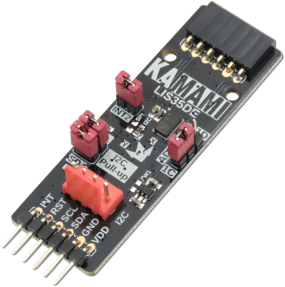
Basic features and parameters
- LIS35DE (MEMS accelerometer) from STMicroelectronics
- Measuring range: ± 2/± 8 g
- 8-bit data output
- Low power consumption (<1 mW)
- Communication interface: SPI/I2C
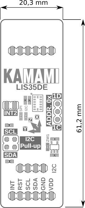
- Configurable I2C bus address: 0x1C or 0x1D
- Programmable interrupt generators (with free fall, motion detection)
- Through-connector compatible with the Pmod standard, allows for serial connection of Pmod I2C modules
- Connector in accordance with the KAMAMI standard
- Built-in jumpers enabling pull-up on I2C bus lines
- Built-in jumper connecting the INT line of the system to the INT line of the Pmod connectors
- Possibility of supply with voltage from 1.9 - 3.6 V via Pmod connector and 1.9 - 5.5 V via KAMAMI connector
- Mounting holes with a diameter of 2.5 mm
- Dimensions: 61.2 mm x 20.3 mm x 10 mm
Standard equipment
| Code | Description |
|---|---|
| KAmodLIS35DE |
|
Electrical schematics
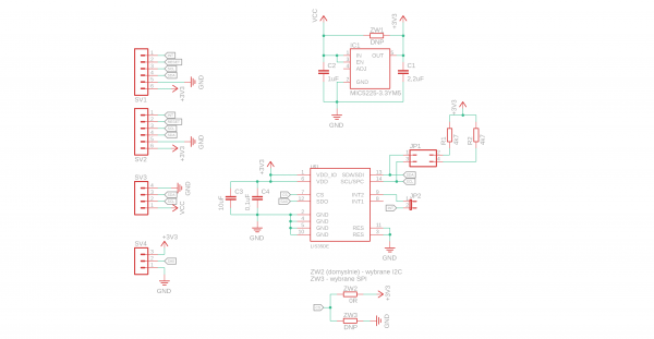
Output description - Pmod standard connector
Output description – KAMAMI standard connector
 |
Pin number | I2C | SPI 3-wire |
|---|---|---|---|
| 1 (VCC) | Power supply (max. 5,5 V) | ||
| 2 (SCL) | I2C clock line | SPI clock line (SPC) | |
| 3 (SDA) | I2C data line | SPI data line (SDI/SDO) | |
| 4 (GND) | Ground | ||
I2C interface line
The KAmodLIS35DE module is equipped with jumpers enabling the connection of pull-up resistors to the power supply to the I2C bus line. Jumpers allow the independent activation for SDA and SCL lines.
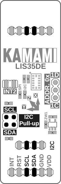
I2C interface address
The KAmodLIS35DE module is equipped with a jumper that allows you to change the I2C bus address. The jumper allows you to switch the address between the value 0x1C and 0x1D.
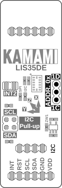
INT interrupt line
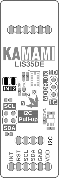
The KAmodLIS35DE module has a jumper to connect the INT2 interrupt output line to the connector compatible with the Pmod standard. Thanks to the ability to disconnect the KAmodLIS35DE interrupt line from the Pmod connectors, the user does not have to worry about the consequences of any conflicts arising from connecting modules compatible with Pmod with different logic states.
Communication bus
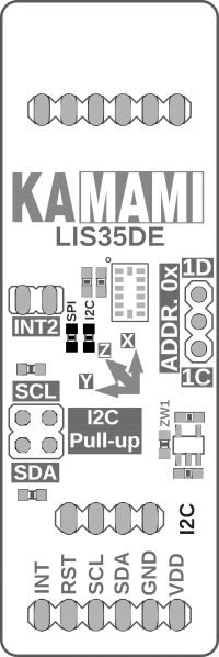
The KAmodLSM303C module has the option of choosing a communication bus between I2C and SPI. The active bus is selected by soldering the jumper in the right place in the form of a 0R resistor on the board. By default, the module is configured for communication via the I2C bus.
Power supply voltage jumper
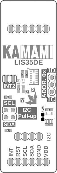
The KAmodLIS35DE module has a jumper that allows the module to be supplied with voltage supplied to the KAMAMI connector without the 3.3 V regulator. To configure the module in this way, solder the ZW1 jumper located next to the regulator.
Dimensions
