KAmodLSM6DS3: Difference between revisions
From Kamamilabs.com - Wiki
m Text replacement - "__jzXpdf__" to "__jzpdf__" |
No edit summary |
||
| (2 intermediate revisions by 2 users not shown) | |||
| Line 2: | Line 2: | ||
====== Description ====== | ====== Description ====== | ||
[https://kamami.pl/kamod-kamami/563464-kamodlsm6ds3-modul-akcelerometru-zyroskopu-z-ukladem-lsm6ds3.html KAmodLSM6DS3] is a module with MEMS LSM6DS3 type. Chip has a digital output (with using I2C or SPI interface) and allow to make a measurement of acceleration and angle velocity in three axis. Thanks to programmable interrupt outputs, it is possible e.g. wake up a microcontroller after free fall detection or object movement. Module can be used in system with power supply 2.5 - 5.5V. | [https://kamami.pl/kamod-kamami/563464-kamodlsm6ds3-modul-akcelerometru-zyroskopu-z-ukladem-lsm6ds3.html KAmodLSM6DS3] is a module with MEMS LSM6DS3 type. Chip has a digital output (with using I2C or SPI interface) and allow to make a measurement of acceleration and angle velocity in three axis. Thanks to programmable interrupt outputs, it is possible e.g. wake up a microcontroller after free fall detection or object movement. Module can be used in system with power supply 2.5 - 5.5V. | ||
<center> | <center> | ||
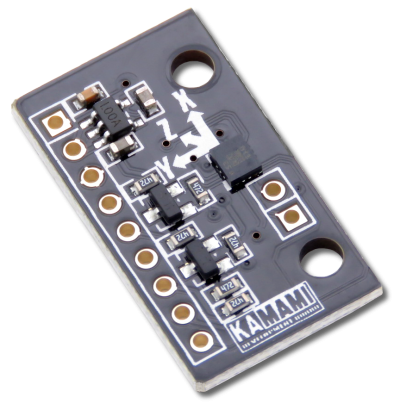
[[File:KAmodLSM6DS3_modul.png|none|400px|thumb|center]] | [[File:KAmodLSM6DS3_modul.png|none|400px|thumb|center]] | ||
| Line 29: | Line 29: | ||
|- | |- | ||
| style="text-align: center;"|<b>KAmodLSM6DS3</b> | | style="text-align: center;"|<b>KAmodLSM6DS3</b> | ||
| style="text-align: | | style="text-align: left;"| | ||
*Assembled and launched module | *Assembled and launched module | ||
*Pin header (male and angle) for soldering | *Pin header (male and angle) for soldering | ||
Latest revision as of 17:20, 1 November 2024

Description
KAmodLSM6DS3 is a module with MEMS LSM6DS3 type. Chip has a digital output (with using I2C or SPI interface) and allow to make a measurement of acceleration and angle velocity in three axis. Thanks to programmable interrupt outputs, it is possible e.g. wake up a microcontroller after free fall detection or object movement. Module can be used in system with power supply 2.5 - 5.5V.

Basic features and parameters
- LSM6DS3 chip (accelerometer and gyroscope) from STMicroelectronics
- Measurement range of accelerometer: ±2 / ±4 / ±8 / ±16g
- Measurement range of gyroscope: ±125 / ±245 / ±500 / ±1000 / ±2000 angle/second (dps)
- Power supply voltage: 2.5V - 5.5V
- Sleep mode / Low power mode
- Communication interface: SPI / I2C
- Embedded voltage regulator and logic level translator (SDA and SCL lines)
- Configurable interrupt generator
- Possibility of subordinate I2C interface connection (I2C HUB)
- Place for soldering of pin header
- Mounting holes 3mm
- Module size (without connector): 27mm x 16mm x 3mm
Standard equipment
| Code | Description |
|---|---|
| KAmodLSM6DS3 |
|
Electrical schematic

Outputs description
 |
JP1 | I2C | SPI 3-wire | SPI 4-wire |
|---|---|---|---|---|
| +3.3V | Module power supply | |||
| +VIN | ||||
| GND | ||||
| SDA | SDA | SDI/SDO | SDI | |
| SCL | SCL | SPC | SPC | |
| SDO/SA0 | SA0 | - | SDO | |
| CS | CS | CS | CS | |
| INT2 | Interrupt 2 output | |||
| INT1 | Interrupt 1 output | |||