KAmodMPC17C724: Difference between revisions
From Kamamilabs.com - Wiki
m Text replacement - "__jzpdf__" to "__jzXpdf__" |
No edit summary Tag: Manual revert |
||
| (2 intermediate revisions by one other user not shown) | |||
| Line 1: | Line 1: | ||
__jzpdf__ | |||
====== Description ====== | ====== Description ====== | ||
[https://kamami.pl/kamod-kamami/563466-kamodmpc17c724-modul-sterownika-silnikow-z-podwojnym-mostkiem-h-mpc17c724.html KAmodMPC17C724] is a module with dual H-Bridge motor driver. H-Bridge chip allows to control two DC motors or one bipolar stepper motor. Controller works with voltage in range 2.7 – 5.5V and can provide motors drive currents of 0.4A. | [https://kamami.pl/kamod-kamami/563466-kamodmpc17c724-modul-sterownika-silnikow-z-podwojnym-mostkiem-h-mpc17c724.html KAmodMPC17C724] is a module with dual H-Bridge motor driver. H-Bridge chip allows to control two DC motors or one bipolar stepper motor. Controller works with voltage in range 2.7 – 5.5V and can provide motors drive currents of 0.4A. | ||
Latest revision as of 18:19, 1 November 2024

Description
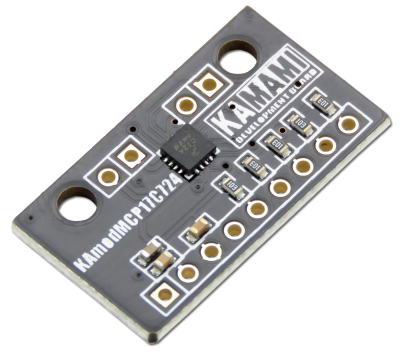
KAmodMPC17C724 is a module with dual H-Bridge motor driver. H-Bridge chip allows to control two DC motors or one bipolar stepper motor. Controller works with voltage in range 2.7 – 5.5V and can provide motors drive currents of 0.4A.

Basic features and parameters
- Chip MPC17C724 from Freescale
- Power supply voltage in range: 2.7V – 5.5V
- Current efficiency: max. 0.4A (pro channel)
- Possibility of control two DC motors or one bipolar stepper motor
- Possibility of using PWM signal with frequency 200kHz
- Possibility of changing rotation direction (dual H-Bridge)
- Possibility of electrodynamic break enabling
- Mounting holes 3mm
- Module size: 27mm x 16mm x 3mm (without connector)
- Weight: 1.4g (without connector)
Standard equipment
| Code | Description |
|---|---|
| KAmodMPC17C724 |
|
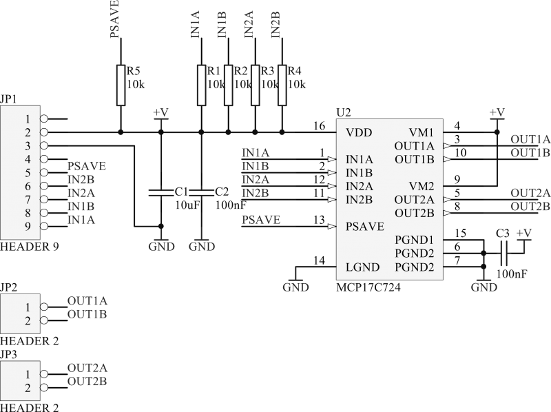
Electrical schematic

Output description
Principle of operation
Truth table of controller KAmodMPC17C724:
| Input lines | Output lines | |||
|---|---|---|---|---|
| PSAVE | IN1A/IN2A | IN1B/IN2B | O1A/O2A | O1B/O2B |
| L | L | L | L | L |
| L | H | L | H | L |
| L | L | H | L | H |
| L | H | H | Z | Z |
| H | X | X | Z | Z |
(description: L- low; H- high; Z – high impedance; X - insignificant)
