KAmodQTR8A: Difference between revisions
From Kamamilabs.com - Wiki
No edit summary |
|||
| (6 intermediate revisions by 3 users not shown) | |||
| Line 2: | Line 2: | ||
====== Description ====== | ====== Description ====== | ||
[https://kamami.pl/czujniki-odbiciowe/557734-kamodqtr8a-modul-z-osmioma-czujnikami-odbiciowymi-ktir0711s.html KAmodQTR8A] is a module with eight photointerrupter sensors KTIR0711S. It allows to detect edge or line. Thanks to the analog outputs, is possible to connect a module to the e.g. comparator. The module can be used in analisze of the floor e.g. by Linefollower vehicles. | [https://kamami.pl/czujniki-odbiciowe/557734-kamodqtr8a-modul-z-osmioma-czujnikami-odbiciowymi-ktir0711s.html KAmodQTR8A] is a module with eight photointerrupter sensors KTIR0711S. It allows to detect edge or line. Thanks to the analog outputs, is possible to connect a module to the e.g. comparator. The module can be used in analisze of the floor e.g. by Linefollower vehicles. | ||
<center> | <center> | ||
[[File:KAmodQTR8A_modul.png|none|400px|thumb|center]] | [[File:KAmodQTR8A_modul.png|none|400px|thumb|center]] | ||
| Line 28: | Line 28: | ||
|- | |- | ||
| style="text-align: center;"|<b>KAmodQTR8A</b> | | style="text-align: center;"|<b>KAmodQTR8A</b> | ||
| style="text-align: | | style="text-align: left;"| | ||
*Assembled and launched module | *Assembled and launched module | ||
*2x straight male headers (2 pin) for soldering | *2x straight male headers (2 pin) for soldering | ||
| Line 39: | Line 39: | ||
===== Electrical schematic ===== | ===== Electrical schematic ===== | ||
<center> | <center> | ||
[[File:KAmodQTR8A_schemat.png|none| | [[File:KAmodQTR8A_schemat.png|none|600px|thumb|center]] | ||
</center> | </center> | ||
| Line 49: | Line 49: | ||
Power supply with a voltage 5V should be connected to the JP3 (VCC, GND) header. By using IrED line can be enabling and disabling LED IR emitters. On outputs CH1…CH8 are extended analog signals from KTIR0711S photointerrupter (by lack of the reflection from the floor, voltage on output is close to power supply voltage). | Power supply with a voltage 5V should be connected to the JP3 (VCC, GND) header. By using IrED line can be enabling and disabling LED IR emitters. On outputs CH1…CH8 are extended analog signals from KTIR0711S photointerrupter (by lack of the reflection from the floor, voltage on output is close to power supply voltage). | ||
<center> | <center> | ||
[[File:KAmodQTR8A_schemat_zlacza_male.png|90px]] | |||
[[File:KAmodQTR8A_schemat_zlacza.png|110px]] | |||
{| class="wikitable" style="width: 600px;" | {| class="wikitable" style="width: 600px;" | ||
| Line 78: | Line 76: | ||
<center> | <center> | ||
<br> | <br> | ||
[[File:KAmodQTR8A_obrys_PCB_czujnik_ext.png|100px]] | |||
[[File:KAmodQTR8A_schemat_czujnik_ext.png|100px]] | |||
[[File:KAmodQTR8A_widok_modułu_odlaczone_sensory.png|none|700px|thumb|center]] | [[File:KAmodQTR8A_widok_modułu_odlaczone_sensory.png|none|700px|thumb|center]] | ||
</center> | </center> | ||
Latest revision as of 18:40, 1 November 2024

Description
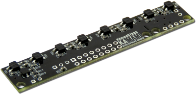
KAmodQTR8A is a module with eight photointerrupter sensors KTIR0711S. It allows to detect edge or line. Thanks to the analog outputs, is possible to connect a module to the e.g. comparator. The module can be used in analisze of the floor e.g. by Linefollower vehicles.
Basic features and parameters
- Photointerrupter type KTIR0711S
- Embedded 8 sensors
- Recommended distance to the floor: 6mm
- Blackout of the sensor is signalizing with voltage close to the zero
- Possibility of cutting a board with two sensor and using it in other application
- Transistor to the IR emitter control allows to e.g. introducing of the modulation
- Power supply voltage: 5V
- Power consumption: 90mA
- Possibility of power supply with 3.3V (BYPASS jumper is needed)
- Holes for headers soldering
- Mounting holes 3mm
- Module size (without connectors): 75mm x 13mm x 3.2mm
Standard equipment
| Code | Description |
|---|---|
| KAmodQTR8A |
|
Electrical schematic
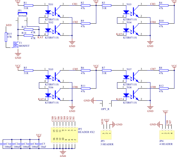
View of PCB

Module power supply and signal outputs
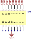
Power supply with a voltage 5V should be connected to the JP3 (VCC, GND) header. By using IrED line can be enabling and disabling LED IR emitters. On outputs CH1…CH8 are extended analog signals from KTIR0711S photointerrupter (by lack of the reflection from the floor, voltage on output is close to power supply voltage).
| JP2/JP3 | Function |
|---|---|
| GND | Ground of the module |
| VCC | Power supply of the module |
| IrED | Control signal of IR diode (active by high state) |
| CH1...CH8 | Analog output signals from photointerrupters |
Detachable module with two sensors
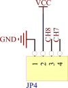
KAmodQTR8A module allows to safety cutting of two sensors (7 and 8 channel) and using in other application. Power supply and output singals are placed on JP4 connectors in this case. In disconnected module should be closed OPT_R connector with a jumper (to the working with 3.3V) or soldered 100Ω resistor (to power supply 5V).

Power supply with voltage 3.3V
By using 3.3V as a power supply voltage should be closed BYPASS connector with a jumper.
Principle of KAmodQTR8A module operation
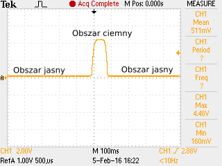
KAmodQTR8A module allow to research of the floor or detect obstacles, which are in rage of working. Eight photointerrupters allow to precise analyzing of the direction in which obstacle or object move (e.g. follow the line in Linefollower vehicles). KTIR0711S sensors (used in module) consist of IR emitter and phototransistor which can react to infrared light. Output of each sensor is an analog signal. Value of the signal depends on amount of reflective light from emitter. In normal state (without reflection) is voltage close to power supply voltage. In case of detection of the reflection on one of the module channel, output voltage of this channel fall close to zero.
