KAmodVL6180X: Difference between revisions
From Kamamilabs.com - Wiki
No edit summary |
No edit summary Tag: Manual revert |
||
| (6 intermediate revisions by 2 users not shown) | |||
| Line 1: | Line 1: | ||
__jzpdf__ | __jzpdf__ | ||
====== | ====== Description ====== | ||
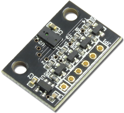
[https://kamami.pl/kamod-kamami/557724-kamodl3gd20-modul-zyroskopu-mems-z-ukladem-l3gd20-firmy-stmicroelectronics.html KAmodVL6180X] to | [https://kamami.pl/kamod-kamami/557724-kamodl3gd20-modul-zyroskopu-mems-z-ukladem-l3gd20-firmy-stmicroelectronics.html KAmodVL6180X] is a module that allows to measure light intensity (ALS), distance to the object and recognition of gesture. It has an embedded voltage regulator and voltage level translators on signal lines. Thanks to this can be used in systems with 2.8V – 5.5V power supply voltage. | ||
<center> | <center> | ||
[[File:KAmodVL6180X_moduł.png|none|400px|thumb|center]] | [[File:KAmodVL6180X_moduł.png|none|400px|thumb|center]] | ||
</center> | </center> | ||
===== | ===== Basic features and parameters ===== | ||
* | *Chip VL6180X from STMicroelectronics | ||
* | *Distance measurement possibility in range from 0 to 100mm | ||
* | *Possibility of light intensity measurement in range from 1 to 100.000 Lux | ||
* | *Power supply voltage: 2.8 – 5.5V | ||
* | *Ocommunication interface: I2C | ||
* | *Two GPIO lines | ||
* | *Embedded voltage regulator and voltage level translators on signal lines | ||
* | *Holes for pin connector soldering | ||
* | *Mounting holes 3mm | ||
* | *Module size (without connector): 24mm x 16mm x 3mm | ||
===== | ===== Standard equipment ===== | ||
<center> | <center> | ||
{| class="wikitable" style="width: 1000px;" | {| class="wikitable" style="width: 1000px;" | ||
|- | |- | ||
! style="text-align: center;"| | ! style="text-align: center;"|Code | ||
! style="text-align: center;"| | ! style="text-align: center;"|Description | ||
|- | |- | ||
| style="text-align: center;"|<b>KAmodVL6180X</b> | | style="text-align: center;"|<b>KAmodVL6180X</b> | ||
| style="text-align: | | style="text-align: left;"| | ||
* | *Assembled and launched module | ||
* | *Pin connector (male and angle) for soldering | ||
|} | |} | ||
</center> | </center> | ||
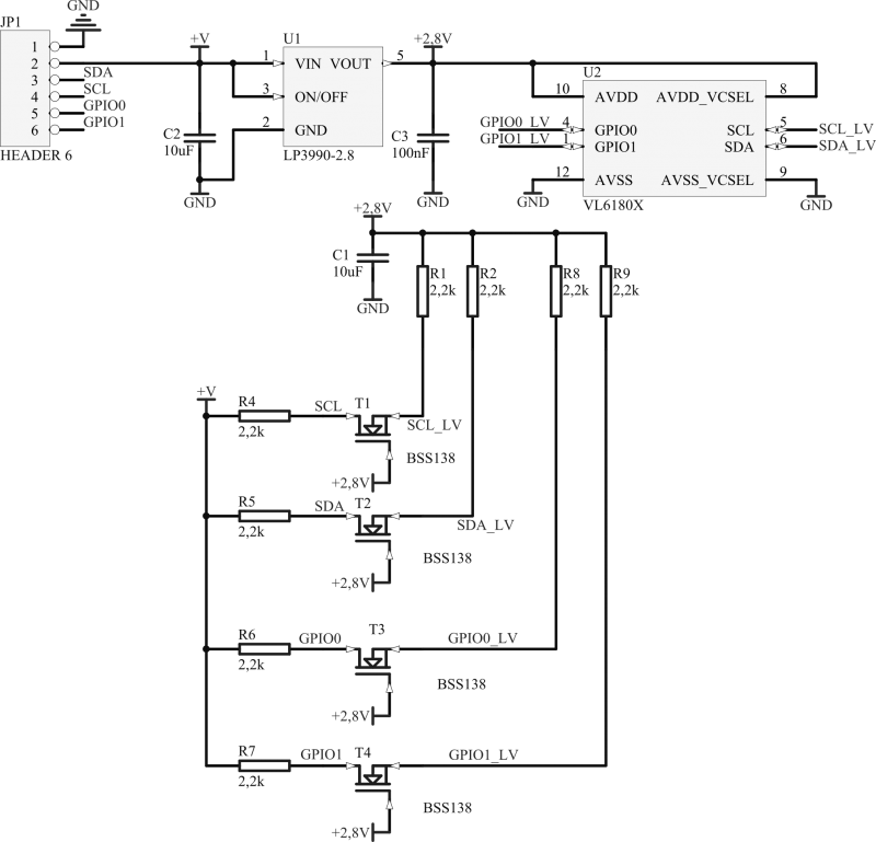
===== | ===== Electrical schematic ===== | ||
<center> | <center> | ||
[[File:KAmodVL6180X_schemat.png|none|800px|thumb|center]] | [[File:KAmodVL6180X_schemat.png|none|800px|thumb|center]] | ||
</center> | </center> | ||
===== | ===== Output description===== | ||
<center> | <center> | ||
| Line 43: | Line 43: | ||
! style="text-align: center;" rowspan="10"| [[File:KAmodVL6180 obrys PCB.png|center|200px]] | ! style="text-align: center;" rowspan="10"| [[File:KAmodVL6180 obrys PCB.png|center|200px]] | ||
! style="text-align: center;"|JP1 | ! style="text-align: center;"|JP1 | ||
! style="text-align: center;"| | ! style="text-align: center;"|Function | ||
|- | |- | ||
| style="text-align: center;"|GND | | style="text-align: center;"|GND | ||
| rowspan="2" colspan="1" style="text-align: center;" | | | rowspan="2" colspan="1" style="text-align: center;" |Module power supply | ||
|- | |- | ||
| style="text-align: center;"|+VIN | | style="text-align: center;"|+VIN | ||
|- | |- | ||
| style="text-align: center;"|SDA | | style="text-align: center;"|SDA | ||
| style="text-align: center;"| | | style="text-align: center;"|I2C Data line | ||
|- | |- | ||
| style="text-align: center;"|SCL | | style="text-align: center;"|SCL | ||
| style="text-align: center;"| | | style="text-align: center;"|I2C Clock line | ||
|- | |- | ||
| style="text-align: center;"|IO0 | | style="text-align: center;"|IO0 | ||
| style="text-align: center;"| | | style="text-align: center;"|Chip Enable/GPIO line | ||
|- | |- | ||
| style="text-align: center;"|IO1 | | style="text-align: center;"|IO1 | ||
| style="text-align: center;"| | | style="text-align: center;"|GPIO1 line | ||
|} | |} | ||
</center> | </center> | ||
===== | ===== External links ===== | ||
*[http://download.kamami.pl/p559362-en.DM00112632.pdf | *[http://download.kamami.pl/p559362-en.DM00112632.pdf VL6180X chip datasheet] | ||
*[http://mikrokontroler.pl/2016/11/15/projekt-kamodvl6180x-kamduino-uno | *[http://mikrokontroler.pl/2016/11/15/projekt-kamodvl6180x-kamduino-uno Article <nowiki>"[PROJEKT] KAmodVL6180X i KAmduino UNO"</nowiki>] | ||
Latest revision as of 09:26, 2 November 2024

Description
KAmodVL6180X is a module that allows to measure light intensity (ALS), distance to the object and recognition of gesture. It has an embedded voltage regulator and voltage level translators on signal lines. Thanks to this can be used in systems with 2.8V – 5.5V power supply voltage.

Basic features and parameters
- Chip VL6180X from STMicroelectronics
- Distance measurement possibility in range from 0 to 100mm
- Possibility of light intensity measurement in range from 1 to 100.000 Lux
- Power supply voltage: 2.8 – 5.5V
- Ocommunication interface: I2C
- Two GPIO lines
- Embedded voltage regulator and voltage level translators on signal lines
- Holes for pin connector soldering
- Mounting holes 3mm
- Module size (without connector): 24mm x 16mm x 3mm
Standard equipment
| Code | Description |
|---|---|
| KAmodVL6180X |
|
Electrical schematic

Output description
 |
JP1 | Function |
|---|---|---|
| GND | Module power supply | |
| +VIN | ||
| SDA | I2C Data line | |
| SCL | I2C Clock line | |
| IO0 | Chip Enable/GPIO line | |
| IO1 | GPIO1 line |