KAmodTXS0108: Difference between revisions
From Kamamilabs.com - Wiki
| (7 intermediate revisions by the same user not shown) | |||
| Line 12: | Line 12: | ||
*Level Shift: Bidirectional | *Level Shift: Bidirectional | ||
*Power Supply: | *Power Supply: | ||
**VCCA from 1. | **VCCA from 1.2 V to +3.6 V, | ||
**VCCB from 1.7 V to +5.5 V, | **VCCB from 1.7 V to +5.5 V, | ||
**VCCA < VCCB | **VCCA < VCCB | ||
*Dimensions: 16 x 29 mm | *Dimensions: 16 x 29 mm | ||
<br><br> | |||
===== Standard Equipment ===== | ===== Standard Equipment ===== | ||
<center> | <center> | ||
| Line 25: | Line 27: | ||
| style="text-align: center;"|<b>KAmodTXS0108</b> | | style="text-align: center;"|<b>KAmodTXS0108</b> | ||
| style="text-align: left;"| | | style="text-align: left;"| | ||
*Assembled and | *Assembled and tested module | ||
|} | |} | ||
</center> | </center> | ||
<br><br> | |||
===== Schematic ===== | ===== Schematic ===== | ||
<center> | <center> | ||
| Line 33: | Line 37: | ||
</center> | </center> | ||
===== Connection ===== | ===== Connection ===== | ||
'''Power supply:''' The converter requires power from two different sources. The higher voltage (from 1.7 V to 5.5 V) should be connected to the pin marked as VCC_B, and the lower voltage (from 1. | '''Power supply:''' The converter requires power from two different sources. The higher voltage (from 1.7 V to 5.5 V) should be connected to the pin marked as VCC_B, and the lower voltage (from 1.2 V to 3.6 V) should be connected to VCC_A.<br> | ||
'''Ground:''' Both devices and the converter must have a common ground, so the ground wire should be connected to the pin marked as GND.<br> | '''Ground:''' Both devices and the converter must have a common ground, so the ground wire should be connected to the pin marked as GND.<br> | ||
'''Logical signals:''' Signals should be connected to the appropriate connectors. Signals with a higher voltage should be connected to the Bx connectors, and signals with a lower voltage to the Ax connectors. <center> | '''Logical signals:''' Signals should be connected to the appropriate connectors. Signals with a higher voltage should be connected to the Bx connectors, and signals with a lower voltage to the Ax connectors. <center> | ||
[[File: | [[File:KAmodTXS0108_conn_EN.png|none|1200px|thumb|center]] | ||
</center> | </center> | ||
<br><br> | |||
===== Dimensions ===== | ===== Dimensions ===== | ||
| Line 45: | Line 50: | ||
</center> | </center> | ||
<br><br> | |||
===== External links ===== | ===== External links ===== | ||
*[https://wiki.kamamilabs.com/images/e/e0/Txs0108e.pdf Texas Instruments TXS108EPW | *[https://download.kamami.pl/p581753-txs0108%20zastosowania.pdf TXS0108 Guide and Applications] | ||
*[https://wiki.kamamilabs.com/images/e/e0/Txs0108e.pdf Texas Instruments TXS108EPW Datasheet] | |||
Latest revision as of 16:15, 1 March 2025

Description
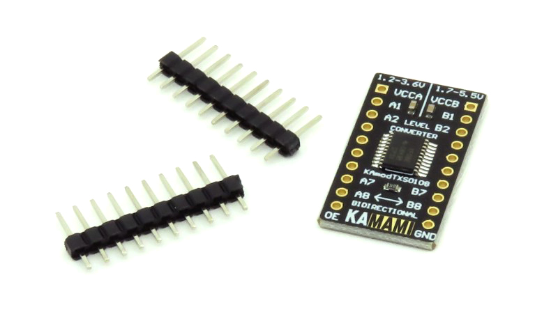
KAmodTXS0108 is a module with the TXS0108 system from Texas Instruments. The system is an 8-channel voltage translator. Thanks to the built-in direction detection system, the module provides two-way signal flow without the need to use an additional pin. Thanks to its small dimensions, the product can be used in many development projects.

Basic Features
- Texas Instruments TXS0108E
- 8 Channels
- Level Shift: Bidirectional
- Power Supply:
- VCCA from 1.2 V to +3.6 V,
- VCCB from 1.7 V to +5.5 V,
- VCCA < VCCB
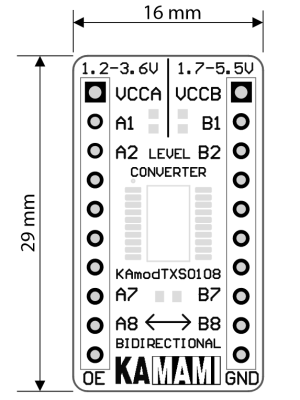
- Dimensions: 16 x 29 mm
Standard Equipment
| Code | Description |
|---|---|
| KAmodTXS0108 |
|
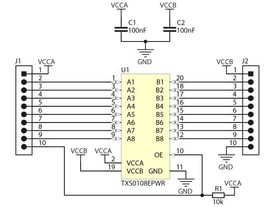
Schematic

Connection
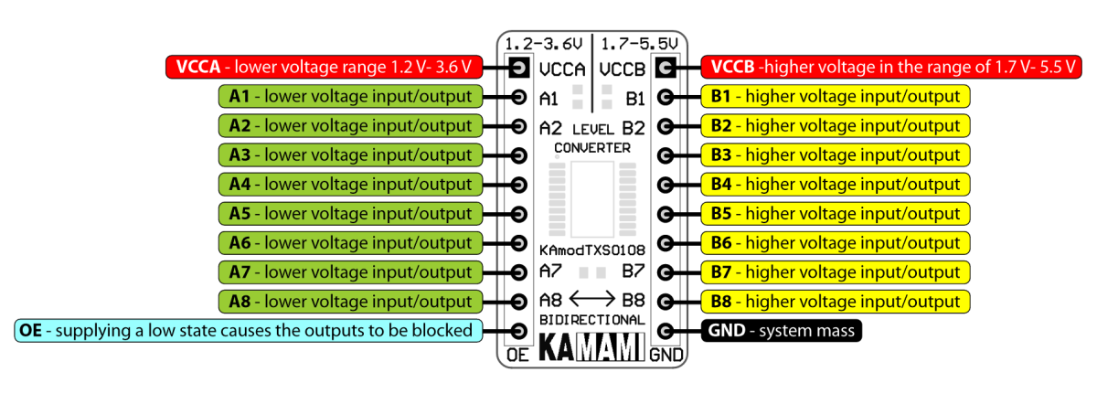
Power supply: The converter requires power from two different sources. The higher voltage (from 1.7 V to 5.5 V) should be connected to the pin marked as VCC_B, and the lower voltage (from 1.2 V to 3.6 V) should be connected to VCC_A.
Ground: Both devices and the converter must have a common ground, so the ground wire should be connected to the pin marked as GND.
Logical signals: Signals should be connected to the appropriate connectors. Signals with a higher voltage should be connected to the Bx connectors, and signals with a lower voltage to the Ax connectors.

Dimensions
