KAmodMMC: Difference between revisions
From Kamamilabs.com - Wiki
m Text replacement - "__jzXpdf__" to "__jzpdf__" |
|||
| (2 intermediate revisions by 2 users not shown) | |||
| Line 1: | Line 1: | ||
__jzpdf__ | __jzpdf__ | ||
===== Description ===== | ===== Description ===== | ||
KAmodMMC Module allows easy and safety connection to any MMC and SD memory card digital system. It provides both compatible connector and bi-directional logic voltage conversion 3.3 V <- > 5 V. | [https://kamami.pl/en/kamod-kamami-peripheral-modules/63663-kamodmmc-5906623433100.html KAmodMMC] Module allows easy and safety connection to any MMC and SD memory card digital system. It provides both compatible connector and bi-directional logic voltage conversion 3.3 V <- > 5 V. | ||
<center> | <center> | ||
[[File: | [[File:kamodmmc_1.jpg|500px]] | ||
[[File:kamodmmc_2.jpg|500px]] | |||
</center> | </center> | ||
| Line 17: | Line 18: | ||
* card insertion indicating LED | * card insertion indicating LED | ||
* jumper for module – system terminals disconnection | * jumper for module – system terminals disconnection | ||
* dimensions: 35 x 60 x 15 mm | |||
===== Standard Equipment ===== | ===== Standard Equipment ===== | ||
Latest revision as of 08:29, 30 July 2025

Description
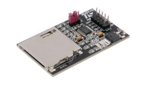
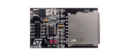
KAmodMMC Module allows easy and safety connection to any MMC and SD memory card digital system. It provides both compatible connector and bi-directional logic voltage conversion 3.3 V <- > 5 V.
Basic Features
- all-purpose interface for SD and MMC cards
- supply voltage: 5 V
- on-board 3.3 V voltage regulator for SD /MMC cards supply
- on-board logic voltage converter
- maximal card clocking frequency: 13 MHz
- supply voltage indicating LED
- card insertion indicating LED
- jumper for module – system terminals disconnection
- dimensions: 35 x 60 x 15 mm
Standard Equipment
| Code | Description |
|---|---|
| KAmodMMC |
|
Schematic
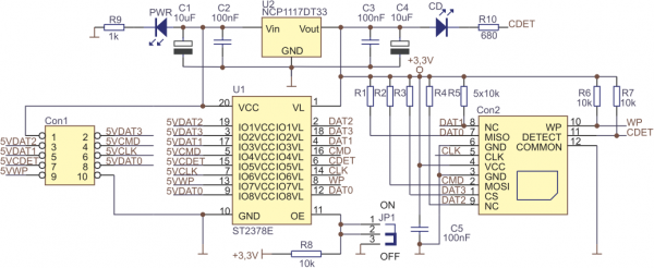
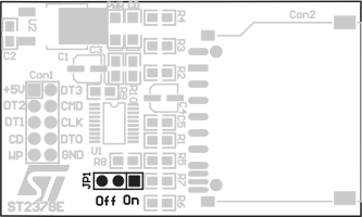
Board Layout
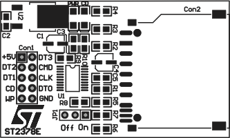
Module Connection
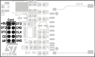
CON1 connector description (according to 5V TTL and 3.3V TTL voltage levels)
| Contact No. | Contacts assignment | Description (SD) | Description (MMC) | Connecting designation |
|---|---|---|---|---|
| 1 | +5 V | (+) of supply voltage (5V recommended) | (+) of supply voltage (5V recommended) | Supply |
| 2 | DAT3 (CD/DAT3)/(DT3) | D3 data line | ChipSelect (0 active) | Input /output |
| 3 | DAT2/(DT2) | D2 data line | - | Input /output |
| 4 | CMD | Command input line | MOSI | Input /output |
| 5 | DAT1/(DT1) | D1 data line | IRQ (option) | Input /output |
| 6 | CLK | Card clock signal input | SCK | Input |
| 7 | CDET | Card in slot insertion signal output (0 active) | Card in slot insertion signal output (0 active) | Output |
| 8 | DAT0/(DT0) | D0 data line | MISO | Input /output |
| 9 | WP | Write protection signal output (0 active) | Write protection signal output (0 active) | Output |
| 10 | GND | Supply ground | Supply ground | Supply |
Indicating LEDs
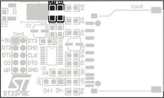
Two indicating LEDs in this module are designed to signalize:
- connected supply – PWR designated LED
- SD or MMC card insertion into Con2 slot-connector – CD designated LED
Module Control
JP1 jumper in this module, allows to connect (On – position) or disconnect (Off – position) SD /MMC card to /from mating system.
