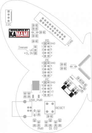
STM32Butterfly: Difference between revisions
From Kamamilabs.com - Wiki
m Text replacement - "__jzXpdf__" to "__jzpdf__" |
|||
| (3 intermediate revisions by 3 users not shown) | |||
| Line 1: | Line 1: | ||
__jzpdf__ | __jzpdf__ | ||
===== Description ===== | ====== Description ====== | ||
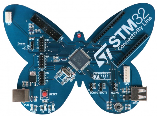
STM32 Butterfly is simple evaluation board equipped with STM32 Connectivity Line microcontroller. | [https://kamami.pl/en/stm32-development-kits/178507-stm32butterfly2-development-kit-with-stm32f107-microcontroller-5906623432332.html STM32 Butterfly] is simple evaluation board equipped with STM32 Connectivity Line microcontroller. | ||
<center> | <center> | ||
[[File:motylek_STM32.jpg|none|600px|thumb|center]] | [[File:motylek_STM32.jpg|none|600px|thumb|center]] | ||
</center> | </center> | ||
===== Introduction ===== | ===== Introduction ===== | ||
Latest revision as of 10:09, 2 November 2024

Description
STM32 Butterfly is simple evaluation board equipped with STM32 Connectivity Line microcontroller.
Introduction
STM32 Butterfly is versatile evaluation board designed for development of applications with STM32F107 microcontrollers (``Connectivity Line`` family). It can also be used as educational board for learning of ARM Cortex-M3 based microcontrollers programming.
Features
- STM32F107VBT6 (LQFP100) microcontroller (128kB Flash, 48kB SRAM, 2xSPI, 1xI2C, 5xUART, USB-OTG, 2xCAN, MAC Ethernet, ADC, 2xDAC)
- 5-position joystick
- 2 LEDs
- 20-pin JTAG connector for programming/debugging
- USB On-the-go socket
- Built-in USB power switch
- 24 GPIO lines
- Connector for PHY module (ZL2ETH)
- I2C connector
- SPI connector
- Optional 32.768kHz generator
- Jumpers for boot memory selection
- Connector for current consumption measurement
- Powered from USB
Standard equipment
| Code | Description |
|---|---|
| STM32Butterfly |
|
Schematics
Power supply
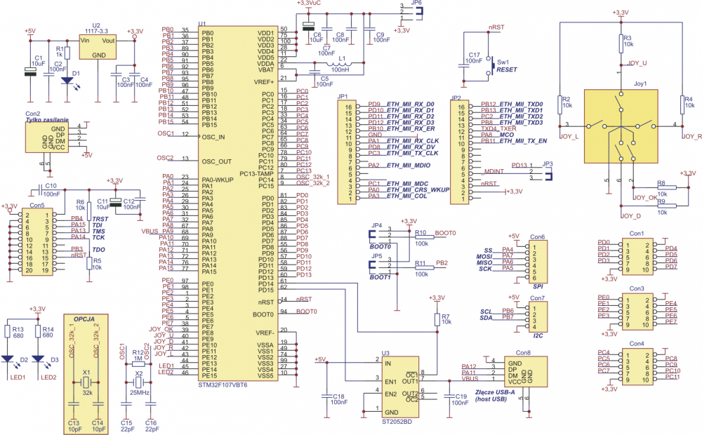
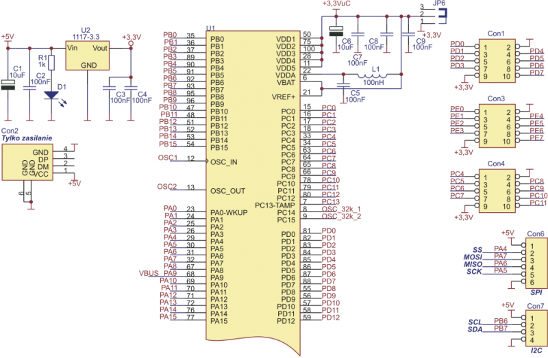
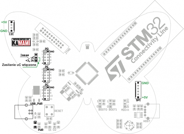
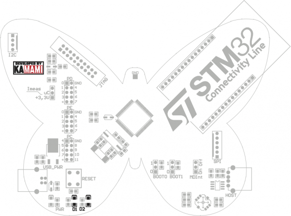
STM32Butterfly board can be powered from the USB port of your PC (Con2 connector). LED D1 indicates power supply. Board is equipped with +3,3V voltage regulator. +3.3V voltage is available on GPIO pin headers, +5V is available on SPI (Con6) and I2C (Con7) connectors. Microcontroller power supply is connected via JP6 jumper (Imeas), that can be used to measure current consumption
Joystick
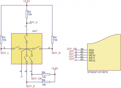
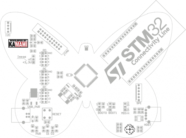
STM32Butterfly is equipped with 5-position joystick. Each position has pull-up resistor. Joystick lines are connected to 8...12 lines of port E.
Ethernet interface
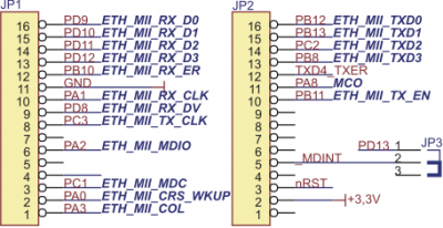
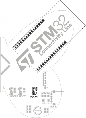
STM32Butterfly has connector for PHY Ethernet module (for example ZL2ETH with STE100P). JP3/MDInt jumper allows connection of PHY module interrupt line to microcontroller 13 line of port D.
LEDs
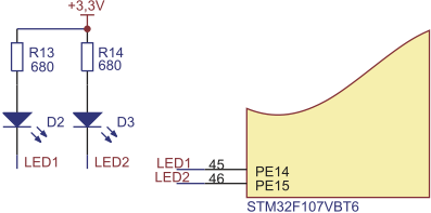
STM32Butterfly is equipped with two LEDs (D2 and D3). They can be lit on with low logic level on GPIO 14 and 15 lines of port of port E.
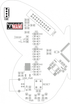
I2C connector
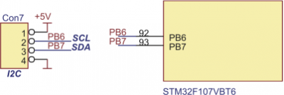
STM32Butterfly is equipped with Con7/I2C connector for external devices with I2C interface. SCL and SDA lines do not have pull-up resistors.
SPI connector
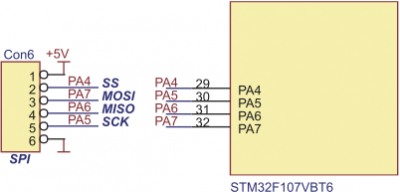
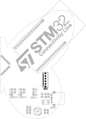
STM32Butterfly is equipped with Con6/SPI connector for external devices with SPI interface. SPI lines do not have pull-up resistors.
USB On-the-go connector
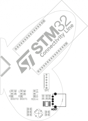
STM32Butterfly is equipped with USB On-the-go port with USB-A socket. Current consumption of USB device connected to board cannot exceed 500 mA.

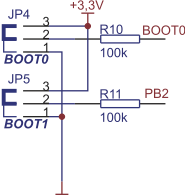
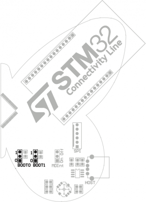
ZBOOT jumpers
STM32Butterfly is equipped with BOOT0 and BOOT1 jumpers that allow selection of boot memory.
| BOOT0 | BOOT1 | Boot mode |
|---|---|---|
| 0 | x | Boot from Flash |
| 1 | 0 | Boot from system memory (bootloader) |
| 1 | 1 | Boot from embedded RAM |
I/O pin headers
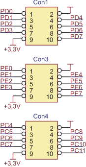
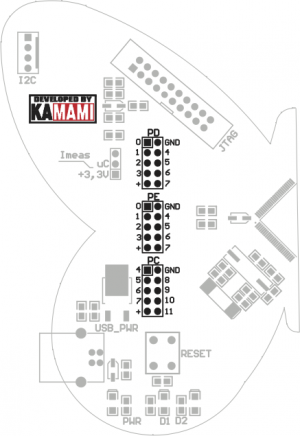
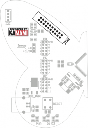
STM32Butterfly is equipped with three 10-pin IDC headers with microcontroller GPIO lines (PC4...11, PD0...7 and PE0...7).
JTAG connector
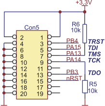
STM32Butterfly is equipped with Con5/JTAG connector for Flash programming/debugging with JTAG interface (for example ZL30PRG).
Optional 32.768kHz generator
STM32Butterfly can be optionally equipped with 32.768 kHz generator and two 10pF capacitors.

