KAmodNFC: Difference between revisions
From Kamamilabs.com - Wiki
Utworzono nową stronę "====== Opis ====== [https://kamami.pl/kamod-kamami/557725-kamodnfc-ekspander-z-nfcrfid-kompatybilny-z-arduino-oraz-nucleo.html KAmodNFC] to płytka rozszerzająca z ukł..." |
|||
| (10 intermediate revisions by 4 users not shown) | |||
| Line 1: | Line 1: | ||
====== | __jzpdf__ | ||
[https://kamami.pl/kamod-kamami/557725-kamodnfc- | ====== Description ====== | ||
[https://kamami.pl/en/kamod-kamami-peripheral-modules/557725-kamodnfc-an-expander-with-nfcrfid-compatible-with-arduino-and-nucleo-5906623433230.html KAmodNFC] is an expansion board with M24LR64E-R chip – dynamic tag with 64kb EEPROM memory and dual communication interface (I2C / RF). On board is placed also signalization of energy harvesting function, which is in M24LR64E-R chip embedded. | |||
<center> | <center> | ||
[[ | [[File:KAmodNFC_modul.png|none|500px|thumb|center]] | ||
</center> | </center> | ||
===== | ===== Basic features and parameters ===== | ||
* | *Chip M24LR64E-R - dynamic NFC tag / RFID from STMicroelectronics | ||
* | *Energy harvesting powers supply line on connector (+Vhr) with effciency max. 7mA | ||
* | *Embedded microstrip antenna, designed for work with frequency 13.56MHz | ||
* | *Connectors compatible with z Arduino UNO R3 | ||
* | *Possibility of using another shield compatible with z Arduino UNO R3 | ||
* | *Embedded tri color user RGB LED | ||
* | *Embedded module of work stabilization with energy harvesting | ||
* | *Mounting hole 3mm | ||
* | *Module size: 74mm x 52mm x 20mm | ||
===== | ===== Standard equipment ===== | ||
<center> | <center> | ||
{| class="wikitable" style="width: 1000px;" | {| class="wikitable" style="width: 1000px;" | ||
|- | |- | ||
! style="text-align: center;"| | ! style="text-align: center;"|Code | ||
! style="text-align: center;"| | ! style="text-align: center;"|Description | ||
|- | |- | ||
| style="text-align: center;"|<b>KAmodNFC</b> | | style="text-align: center;"|<b>KAmodNFC</b> | ||
| style="text-align: | | style="text-align: left;"| | ||
* | *Assembled and launched module | ||
|} | |} | ||
</center> | </center> | ||
===== | |||
===== Electrical schematics ===== | |||
<center> | <center> | ||
[[ | [[File:KAmodNFC_schemat.png|none|800px|thumb|center]] | ||
</center> | </center> | ||
===== | ===== View of PCB ===== | ||
<center> | <center> | ||
[[ | [[File:KAmodNFC_obrys.png|none|400px|thumb|center]] | ||
</center> | </center> | ||
===== | ===== Output description ===== | ||
<center> | <center> | ||
[[ | [[File:KAmodNFC_opis_wyprowadzen.png|none|500px|thumb|center]] | ||
</center> | </center> | ||
===== | |||
M24LR64E-R | ===== M24LR64E-R - tag RFID / NFC chip ===== | ||
M24LR64E-R is a dynamic NFC / RFID tag with 64kb EEPROM memory and dual communication interface – is is possible to use I2C communication bus as well as a radio track. Chip has a energy harvesting function and cooperates with microstrip antenna, which was designed for work with frequency 13.56MHz. | |||
<center> | <center> | ||
[[ | [[File:KAmodNFC_obrys_M24LR64.png|none|400px|thumb|center]] | ||
{| class="wikitable" style="width: 800px;" | {| class="wikitable" style="width: 800px;" | ||
|- | |- | ||
! style="text-align: center;"| | ! style="text-align: center;"|Line | ||
! colspan="2" style="text-align: center;" | | ! colspan="2" style="text-align: center;" |Output | ||
! style="text-align: center;"| | ! style="text-align: center;"|Function | ||
|- | |- | ||
| style="text-align: center;"| | | style="text-align: center;"| | ||
| Line 64: | Line 67: | ||
| style="text-align: center;"|D15 | | style="text-align: center;"|D15 | ||
| style="text-align: center;"|PB8 | | style="text-align: center;"|PB8 | ||
| style="text-align: center;"| | | style="text-align: center;"|Clock line of I2C bus | ||
|- | |- | ||
| style="text-align: center;"|SDA | | style="text-align: center;"|SDA | ||
| style="text-align: center;"|D14 | | style="text-align: center;"|D14 | ||
| style="text-align: center;"|PB9 | | style="text-align: center;"|PB9 | ||
| style="text-align: center;"| | | style="text-align: center;"|Data line of I2C bus | ||
|- | |- | ||
| style="text-align: center;"|RFWIP/BUSY | | style="text-align: center;"|RFWIP/BUSY | ||
| style="text-align: center;"|D12 | | style="text-align: center;"|D12 | ||
| style="text-align: center;"|PA6 | | style="text-align: center;"|PA6 | ||
| style="text-align: center;"| | | style="text-align: center;"|Write / busy signalization | ||
|} | |} | ||
[[ | [[File:KAmodNFC_schemat_M24LR64.png|none|800px|thumb|center]] | ||
</center> | </center> | ||
===== | ===== Multicolor user LED ===== | ||
Embedded RGB user LED in SMD 5060 package make possible to signaling a variety of events by using three, controlled independent colors (red, green, blue). | |||
<center> | <center> | ||
[[ | [[File:KAmodNFC_obrys_dioda.png|none|400px|thumb|center]] | ||
| Line 92: | Line 94: | ||
{| class="wikitable" style="width: 800px;" | {| class="wikitable" style="width: 800px;" | ||
|- | |- | ||
! style="text-align: center;"| | ! style="text-align: center;"|Line | ||
! colspan="2" style="text-align: center;" | | ! colspan="2" style="text-align: center;" |Output | ||
! style="text-align: center;"| | ! style="text-align: center;"|Function | ||
|- | |- | ||
| style="text-align: center;"| | | style="text-align: center;"| | ||
| Line 104: | Line 106: | ||
| style="text-align: center;"|D5 | | style="text-align: center;"|D5 | ||
| style="text-align: center;"|PB4 | | style="text-align: center;"|PB4 | ||
| style="text-align: center;"| | | style="text-align: center;"|Red LED color | ||
|- | |- | ||
| style="text-align: center;"|RGB LED G | | style="text-align: center;"|RGB LED G | ||
| style="text-align: center;"|D4 | | style="text-align: center;"|D4 | ||
| style="text-align: center;"|PB5 | | style="text-align: center;"|PB5 | ||
| style="text-align: center;"| | | style="text-align: center;"|Green LED color | ||
|- | |- | ||
| style="text-align: center;"|RGB LED B | | style="text-align: center;"|RGB LED B | ||
| style="text-align: center;"|D2 | | style="text-align: center;"|D2 | ||
| style="text-align: center;"|PA10 | | style="text-align: center;"|PA10 | ||
| style="text-align: center;"| | | style="text-align: center;"|Blue LED color | ||
|} | |} | ||
[[ | [[File:KAmodNFC_schemat_dioda.png|none|300px|thumb|center]] | ||
</center> | </center> | ||
===== | ===== Energy harvesting ===== | ||
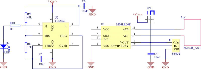
In chip M24LR64E-R embedded function of energy harvesting allows to wireless power supply of devices with low power consumption (max. 7mA), when antenna of module is placed enough near from transmitter antenna (which use CR95HF chip). Power supply with harvesting energy is activated with using jumper “Harvesting Power”. Indicator starts periodically blinking with D2 LED, when on line +Vhr appears harvesting voltage from RF track. | |||
<center> | <center> | ||
[[ | [[File:KAmodNFC_obrys_EH.png|none|400px|thumb|center]] | ||
[[ | [[File:KAmodNFC_schemat_EH.png|none|800px|thumb|center]] | ||
</center> | </center> | ||
===== | ===== Media ===== | ||
Video with presentation of KamodNFC module working | |||
<center><HTML5video type="youtube" width="560" height="315" autoplay="false">me2BXKv3npU</HTML5video></center> | <center><HTML5video type="youtube" width="560" height="315" autoplay="false">me2BXKv3npU</HTML5video></center> | ||
===== | ===== External links ===== | ||
*[http://download.kamami.pl/p557725-KAmodNFC_M24LR64E_DS.pdf | *[http://download.kamami.pl/p557725-KAmodNFC_M24LR64E_DS.pdf M24LR64E-R chip datasheet] | ||
*[http://microgeek.eu/viewtopic.php?f=81&t=462 | *[http://microgeek.eu/viewtopic.php?f=81&t=462 Thread dedicated to the KamodNFC module on site microgeek.eu] | ||
Latest revision as of 18:25, 1 November 2024

Description
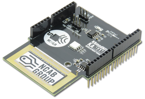
KAmodNFC is an expansion board with M24LR64E-R chip – dynamic tag with 64kb EEPROM memory and dual communication interface (I2C / RF). On board is placed also signalization of energy harvesting function, which is in M24LR64E-R chip embedded.
Basic features and parameters
- Chip M24LR64E-R - dynamic NFC tag / RFID from STMicroelectronics
- Energy harvesting powers supply line on connector (+Vhr) with effciency max. 7mA
- Embedded microstrip antenna, designed for work with frequency 13.56MHz
- Connectors compatible with z Arduino UNO R3
- Possibility of using another shield compatible with z Arduino UNO R3
- Embedded tri color user RGB LED
- Embedded module of work stabilization with energy harvesting
- Mounting hole 3mm
- Module size: 74mm x 52mm x 20mm
Standard equipment
| Code | Description |
|---|---|
| KAmodNFC |
|
Electrical schematics
View of PCB

Output description
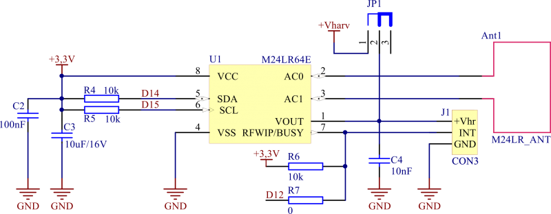
M24LR64E-R - tag RFID / NFC chip
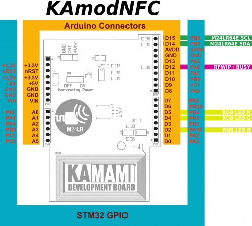
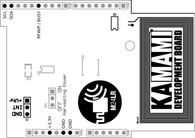
M24LR64E-R is a dynamic NFC / RFID tag with 64kb EEPROM memory and dual communication interface – is is possible to use I2C communication bus as well as a radio track. Chip has a energy harvesting function and cooperates with microstrip antenna, which was designed for work with frequency 13.56MHz.
| Line | Output | Function | |
|---|---|---|---|
| Arduino | STM32 | ||
| SCL | D15 | PB8 | Clock line of I2C bus |
| SDA | D14 | PB9 | Data line of I2C bus |
| RFWIP/BUSY | D12 | PA6 | Write / busy signalization |
Multicolor user LED
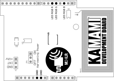
Embedded RGB user LED in SMD 5060 package make possible to signaling a variety of events by using three, controlled independent colors (red, green, blue).
| Line | Output | Function | |
|---|---|---|---|
| Arduino | STM32 | ||
| RGB LED R | D5 | PB4 | Red LED color |
| RGB LED G | D4 | PB5 | Green LED color |
| RGB LED B | D2 | PA10 | Blue LED color |
Energy harvesting
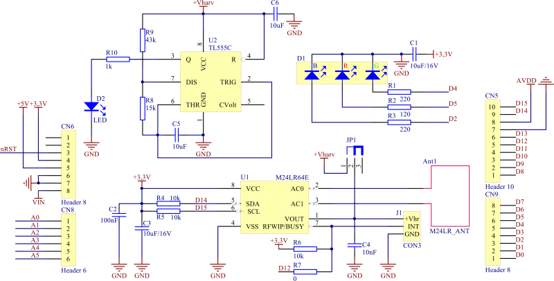
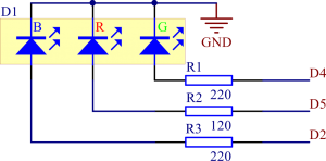
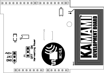
In chip M24LR64E-R embedded function of energy harvesting allows to wireless power supply of devices with low power consumption (max. 7mA), when antenna of module is placed enough near from transmitter antenna (which use CR95HF chip). Power supply with harvesting energy is activated with using jumper “Harvesting Power”. Indicator starts periodically blinking with D2 LED, when on line +Vhr appears harvesting voltage from RF track.
Media
Video with presentation of KamodNFC module working