ZL15AVR: Difference between revisions
From Kamamilabs.com - Wiki
Anna Kubacka (talk | contribs) Created page with "__jzpdf__ ====== Description ====== ZL15AVR is an universal development board for ATmega32 (and other AVR microcontrollers in 40-pin package). With a wide range of peripheral..." |
Anna Kubacka (talk | contribs) No edit summary |
||
| (3 intermediate revisions by the same user not shown) | |||
| Line 3: | Line 3: | ||
====== Description ====== | ====== Description ====== | ||
ZL15AVR is an universal development board for ATmega32 (and other AVR microcontrollers in 40-pin package). With a wide range of peripherals it can be used as an environment for development of prototypes or as an education board. | ZL15AVR is an universal development board for ATmega32 (and other AVR microcontrollers in 40-pin package). With a wide range of peripherals it can be used as an environment for development of prototypes or as an education board. | ||
<center> | <center> | ||
[[File:ZL15AVR.jpg|none|500px|thumb|center]] | [[File:ZL15AVR.jpg|none|500px|thumb|center]] | ||
| Line 206: | Line 206: | ||
<center> | <center> | ||
[[File: | [[File:Lcd12864_neg_black.jpg|none|300px|thumb|center]] | ||
</center> | </center> | ||
<center> | <center> | ||
[[File: | [[File:LCD tylny.jpg|none|300px|thumb|center]] | ||
</center> | </center> | ||
| Line 229: | Line 229: | ||
<center> | <center> | ||
[[File: | [[File:LCD_widok_15.jpg|none|400px|thumb|center]] | ||
</center> | </center> | ||
<center> | <center> | ||
[[File: | [[File:Lcd12864 szpilki.jpg|none|400px|thumb|center]] | ||
</center> | </center> | ||
Latest revision as of 09:27, 24 September 2020

Description
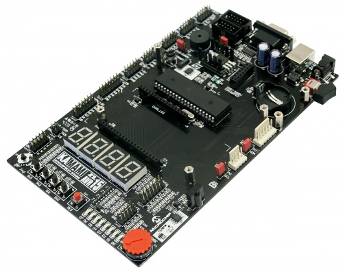
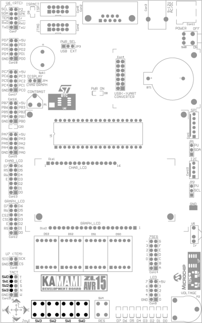
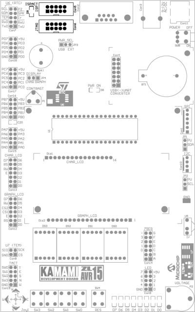
ZL15AVR is an universal development board for ATmega32 (and other AVR microcontrollers in 40-pin package). With a wide range of peripherals it can be used as an environment for development of prototypes or as an education board.
Preface
The ZL15AVR board, thanks to its rich set of peripherals, can be used as environment for developing applications for ATmega32 microcontrollers and other in 40-pin package.
Basic features
- ATmega32 microcontroller in DIP package
- 4 switch keyboard
- 5-position joystick
- 8 LEDs
- four digit seven segment display
- connector for 2x16 characters LCD display (LCD1602)
- connector for graphic LCD display with KS0108 controller IC (LCD12864)
- M41T00 real time clock with socket for CR2032 battery
- TC77 digital thermometer with SPI interface
- thermistor
- TSOP31236 (36kHz) infrared receiver
- piezoelectric speaker
- connector for ZL1USB/ZL4USB module (USB<->UART converter)
- ISP connector
- JTAG connector
- USB connector for powering from PC
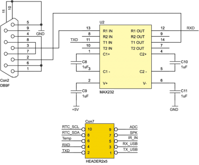
- DB9 connector with MAX232 voltage translator for RS232 transmission
- set of pin connectors with all I/O signals of microcontroller
- potentiometer
Standard equipment
| Kod | Opis |
|---|---|
| ZL15AVR |
|
Electric schematic
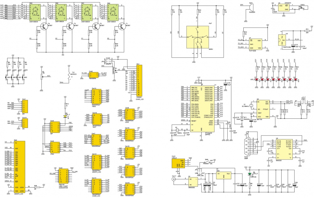
Power supply
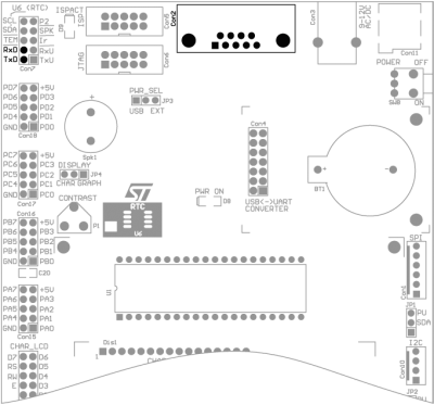
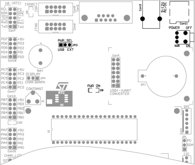
The ZL15AVR board can be powered from the USB port of your PC (USB-B Con3, PWR_SEL pin header in the USB position) or an external voltage source with a value 9..12V (DC connector Con11, PWR_SEL pin header in position EXT). Board is equipped with a switch SW8 which allows to disconnect power without removing the plug from the connector Con3 or Con11. LED D8 indicates the inclusion of the supply voltage.

Keyboard
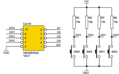
The ZL15AVR board is equipped with four switch keyboard (SW0-SW3). Each button has its own pull-up resistor. Switch lines are available on Con8 connector.
Joystick
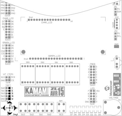
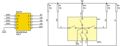
The ZL15AVR board is equipped with 5-position joystick. Each position has its own pull-up resistor. Joystick lines are available on Con19 connector.
LEDs
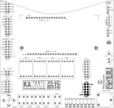
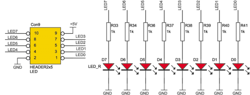
The ZL15AVR board is equipped with 8 LEDs (active state: high). Control lines for LEDs are available on Con9 connector.
LED display
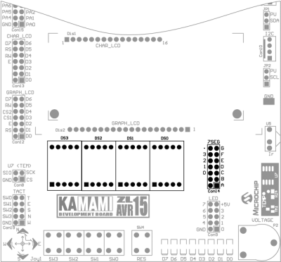
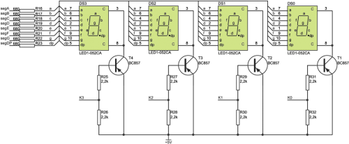
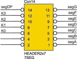
The ZL15AVR board is equipped with four-digit seven segment LED display (DS0-DS3). Control signals for LED display are available on Con14 connector.
Potentiometer
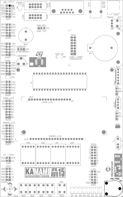
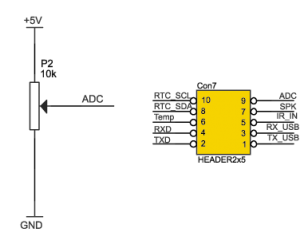
The ZL15AVR board is equipped with potentiometer, which can be used for setting voltage on input of analog to digital converter. The slider of potentiometer is available on Con7 connector (marked as P2).
TC77 digital thermometer
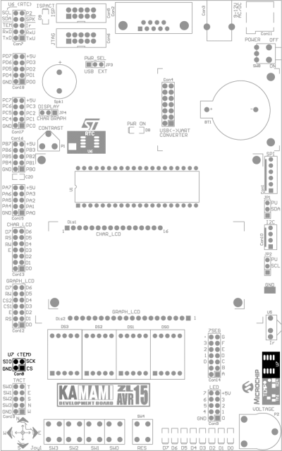
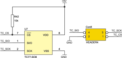
The ZL15AVR board is equipped with TC77 digital thermometer device (Microchip). TC77 device works on SPI bus. SPI lines (SCK, SIO, CS) are available on Con8 connector.
Thermistor
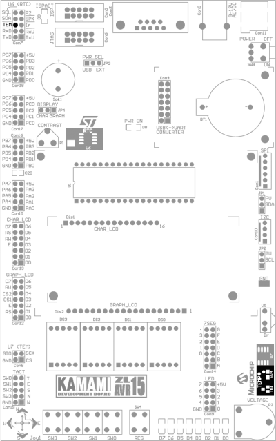
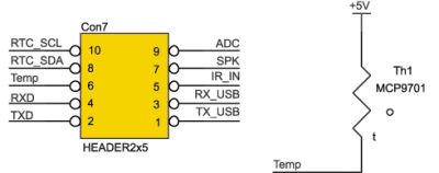
The ZL15AVR board is also equipped with thermistor MCP9701 (Microchip) Output voltage is available on Con7 connector (marked TEM).
Infrared receiver
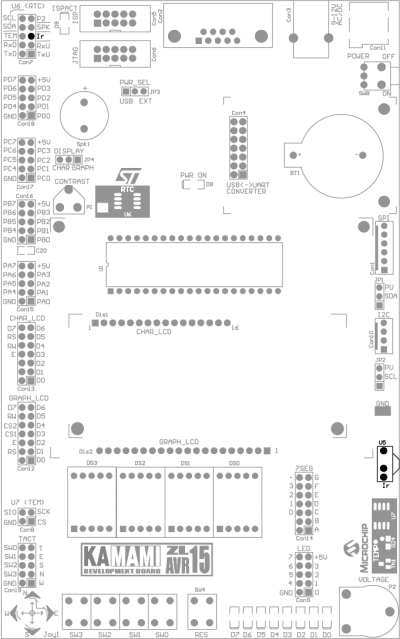
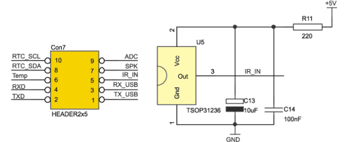
The ZL15AVR board is equipped with TSOP31236 infrared receiver (36kHz). This device can be used to receiving signals sent by RTV equipment remote controllers. Receiver output is available on Con7 connector (marked as Ir).
Connector for graphic LCD display
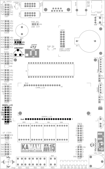
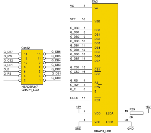
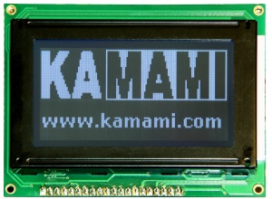
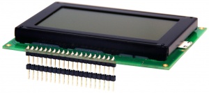
The ZL15AVR board is equipped with connector for graphic LCD display with KS0108 controller (LCD12864). Display’s contrast can be adjusted by P1 potentiometer (JP4 DISPLAY pin header in GRAPH position). Control signals for display are available on Con12 connector.
Connector for alphanumerical LCD display
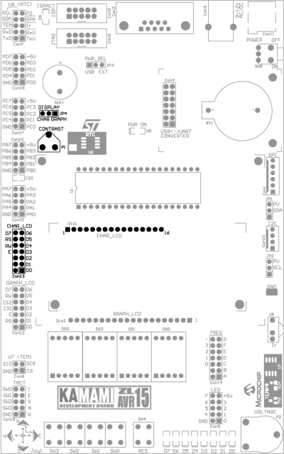
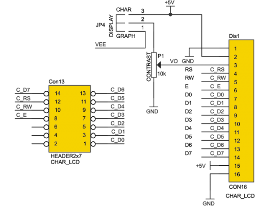
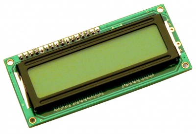
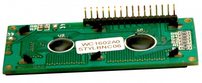
The ZL15AVR board is equipped with connector for alphanumerical LCD display with HD44780 controller (LCD1602). Display contrast can be adjusted by P1 potentiometer (JP4 DISPLAY pin header in CHAR position). Control signals for display are available on Con13 connector.
I2C bus connector
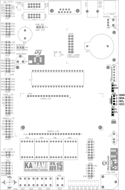
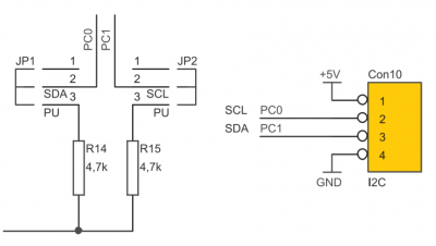
The ZL15AVR board is equipped with connector Con10/I2C which can be used for connecting external devices with I2C interface. It is possible to connect pull-up resistor by using JP1 and JP2 pin header in PU/SDA and PU/SCL positions.
SPI bus connector
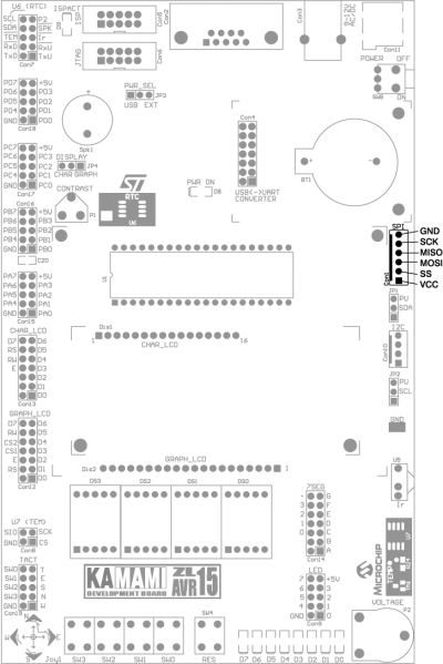
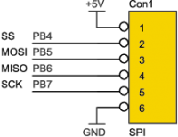
The ZL15AVR board is equipped with connector Con1/SPI which can be used for connecting external devices with SPI interface.
USB<->UART converter connector
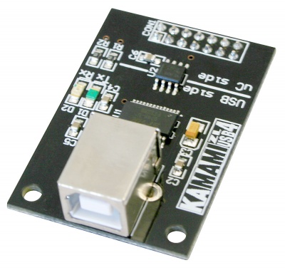
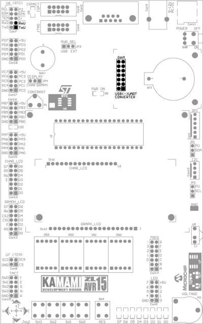
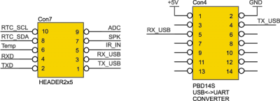
The ZL15AVR board is equipped with connector Con4 which can be used for connecting USB<->UART converter module (for example: ZL1USB_A, ZL4USB). UART lines are available on Con7 connector (marked as TxU and RxU).
M41T00 real time clock device
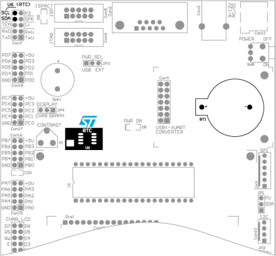
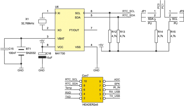
The ZL15AVR board is equipped with M41T00 RTC device. In addition to RTC device on the board there are also socket for battery (CR2032) and crystal oscillator. Control signals (SDA and SCL) are available on Con7 connector.
Buzzer
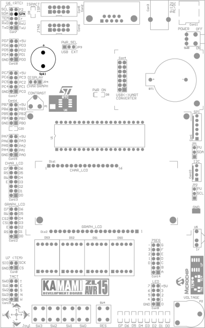
The ZL15AVR board is equipped with piezoelectric buzzer Spk1. Control signal for buzzer is available on Con7 connector (marked as SPK).

JTAG and ISP connectors
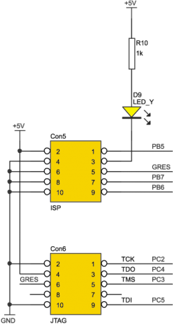
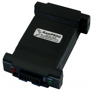
The ZL15AVR board is equipped with Con6 connector which can be used for programming and debugging using JTAG interface (for example: ZL16PRG). Before connecting JTAG tool make sure that PC port is not connected with any low impedance load circuits. If JTAG is enabled, lines TCK, TDI, TDO and TMS are unavailable for other purposes. The ZL15AVR board is equipped with Con5 connector which can be used for programming using ISP interface (for example: ZL20PRG, ZL2PRG). Before connecting ISP tool make sure that lines PB5...PB7 are not connected with any low impedance load circuits.
RS232 connector
The ZL15AVR board is equipped with DB9F connector (Con2). This connector can be used to exchange data with PC by RS232 interface. RxD and TxD signals are available on Con7 connector.
