KAmodMicroSD: Difference between revisions
From Kamamilabs.com - Wiki
| (2 intermediate revisions by 2 users not shown) | |||
| Line 14: | Line 14: | ||
*2.54mm goldpin connector | *2.54mm goldpin connector | ||
*Power supply: 3.7V to 5V | *Power supply: 3.7V to 5V | ||
*Dimensions: 20 x 45 x 10 mm | |||
===== Standard equipment ===== | ===== Standard equipment ===== | ||
| Line 24: | Line 24: | ||
|- | |- | ||
| style="text-align: center;"|<b>KAmodMicroSD module</b> | | style="text-align: center;"|<b>KAmodMicroSD module</b> | ||
| style="text-align: | | style="text-align: left;"| | ||
*Assembled and launched module | *Assembled and launched module | ||
|} | |} | ||
| Line 43: | Line 43: | ||
! style="text-align: center;"|Function | ! style="text-align: center;"|Function | ||
|- | |- | ||
| style="text-align: center;"|(Pin | | style="text-align: center;"|(1st Pin) VCC | ||
| style="text-align: center;" |Power supply | | style="text-align: center;" |Power supply | ||
|- | |- | ||
Latest revision as of 08:35, 30 July 2025

Description
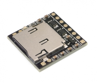
KAmodMicroSD is a module with a micro SD (TF) card reader. It allows you to connect and operate popular memory cards using a microcontroller. It is commonly used in various devices to store images, sounds or measurement data. On the board there is a 3.3 V voltage regulator and a voltage level converter enabling operation with 3.3 V and 5 V systems. For communication, the module uses the SPI interface available on the connector with a pitch of 2.54 mm.

Basic features
- Micro SD card slot
- SPI interface
- 3.3V 250mA voltage regulator
- 3.3V/5V voltage level converter
- 2.54mm goldpin connector
- Power supply: 3.7V to 5V
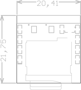
- Dimensions: 20 x 45 x 10 mm
Standard equipment
| Code | Description |
|---|---|
| KAmodMicroSD module |
|
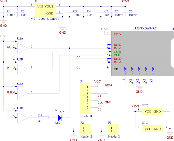
Schematic

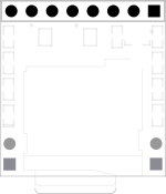
Output description - P1 connector
 |
P1 | Function |
|---|---|---|
| (1st Pin) VCC | Power supply | |
| +3V3 | 3,3 V | |
| GND | GND | |
| CS | CS signal | |
| DI | Data input | |
| CLK | Clock | |
| DO | Data output | |
| CD | CD signal |
Dimensions
