KAmod Motor Driver: Difference between revisions
From Kamamilabs.com - Wiki
| (14 intermediate revisions by the same user not shown) | |||
| Line 1: | Line 1: | ||
__jzpdf__ | __jzpdf__ | ||
===== Description ===== | ====== Description ====== | ||
The <b>KAmod Motor Driver </b> is an electric motor controller for DC voltages up to 30 V. It allows the selection of the motor's direction of rotation and the adjustment of its power in the range 0...100%, which in practice is used for speed control. The control signal can be a voltage signal falling within one of 3 ranges: 0...3.3 V, 0...5 V or 0...10 V, or a PWM signal with an amplitude of 3.3 V, 5 V or 10 V. Such signals can be easily obtained from Raspberry, Arduino, Nucleo boards or from a simple potentiometer. The power stage is built with MOSFET transistors connected in an H-bridge arrangement, which ensures high output power and high efficiency of the controller. | The <b>[https://kamami.pl/en/Motor-controllers/1189218-kamod-motor-driver-universal-electric-motor-controller-5906623432929.html KAmod Motor Driver] </b> is an electric motor controller for DC voltages up to 30 V. It allows the selection of the motor's direction of rotation and the adjustment of its power in the range 0...100%, which in practice is used for speed control. The control signal can be a voltage signal falling within one of 3 ranges: 0...3.3 V, 0...5 V or 0...10 V, or a PWM signal with an amplitude of 3.3 V, 5 V or 10 V. Such signals can be easily obtained from Raspberry, Arduino, Nucleo boards or from a simple potentiometer. The power stage is built with MOSFET transistors connected in an H-bridge arrangement, which ensures high output power and high efficiency of the controller. | ||
<center> | <center> | ||
[[File:KAmod_Motor_Driver_f1.jpg|none|900px|thumb|center]] | [[File:KAmod_Motor_Driver_f1.jpg|none|900px|thumb|center]] | ||
| Line 37: | Line 37: | ||
</center> | </center> | ||
===== | ===== Electrical schematics ===== | ||
<center> | <center> | ||
[[File:Sch_motor_uc.jpg|none|800px|thumb|center]] | [[File:Sch_motor_uc.jpg|none|800px|thumb|center]] | ||
| Line 50: | Line 50: | ||
</center> | </center> | ||
===== | ===== Output power control ===== | ||
<center> | <center> | ||
{| class="wikitable" style="width: 1000px;" | {| class="wikitable" style="width: 1000px;" | ||
|- | |- | ||
! style="text-align: center;"| | ! style="text-align: center;"|Connector | ||
! style="text-align: center;"| | ! style="text-align: center;"|Function | ||
|- | |- | ||
| style="text-align: center;"|<b>ADJ IN</b> | | style="text-align: center;"|<b>ADJ IN</b> | ||
Goldpin pins 3x1, 2,54 mm | |||
| style="text-align: left;"| | | style="text-align: left;"| | ||
* | * Analog or digital control signal input | ||
* | * An analog signal is a voltage with an appropriate range of changes | ||
* | * The digital signal is a PWM signal with adjustable duty cycle | ||
* | * The connector has a voltage of 3.3 V | ||
|} | |} | ||
</center> | </center> | ||
The <b>ADJ IN</b> connector pins perform the following functions: | |||
:* <b>V</b> (pin 1, | :* <b>V</b> (pin 1, right) – 3.3 V voltage output that can be loaded with a current of up to 10 mA; | ||
:* <b>S</b> (pin 2, | :* <b>S</b> (pin 2, middle) – analog or digital signal input, the maximum input voltage cannot exceed 16V; | ||
:* <b>G</b> (pin 3, | :* <b>G</b> (pin 3, left) –ground of the system, the ground of the control signal should be connected. | ||
The supplied analog signal must be in one of the 3 control ranges: 0...3.3 V; 0...5 V or 0...10 V. The output power of the motor controller will be proportional to the voltage applied to the <b>S</b> contact and depends on the selected control range. You can connect an ordinary potentiometer to the V, S, G contacts of the connector and thus regulate the output power. | |||
<br><br> | <br><br> | ||
Digital signal - PWM can have a frequency ranging from 200 Hz to 50 kHz, a duty cycle ranging from 0 to 100% and an amplitude of 3.3 V, 5 V or 10 V. The output power of the motor controller will be proportional to the duty cycle of the PWM signal . | |||
<br><br> | <br><br> | ||
The control range for both analog and digital signals is selected using the <b>IN.RNG</b> connector. | |||
<br><br> | <br><br> | ||
| Line 81: | Line 81: | ||
</center> | </center> | ||
===== | ===== Selection of the control signal amplitude range ===== | ||
<center> | <center> | ||
{| class="wikitable" style="width: 1000px;" | {| class="wikitable" style="width: 1000px;" | ||
|- | |- | ||
! style="text-align: center;"| | ! style="text-align: center;"|Connector | ||
! style="text-align: center;"| | ! style="text-align: center;"|Function | ||
|- | |- | ||
| style="text-align: center;"|<b>IN.RNG</b> | | style="text-align: center;"|<b>IN.RNG</b> | ||
Goldpin pins 4x1, 2.54 mm | |||
| style="text-align: left;"| | | style="text-align: left;"| | ||
* | * Setting the voltage range for analog and digital control signals | ||
|} | |} | ||
</center> | </center> | ||
The control signal fed to the <b>ADJ IN</b> connector may come from various systems, development boards and SBC computers. The two most popular standards for the voltage level of digital systems are 3.3 V and 5 V. The analog signal used in home and industrial automation systems is a signal in the range of 0...10 V. In order for the KAmod Motor Driver to work properly with various systems, it must be set the correct voltage range for the control signal. The <b>IN.RNG</b> (input range) connector is used for this purpose. | |||
<br><br> | <br><br> | ||
Setting the jumper in one of 3 positions allows you to select 1 of 3 ranges: | |||
:* | :* valve on pins 1-2: voltage range for the control signal is 10 V; | ||
:* | :* valve on pins 2-3: voltage range for the control signal is 5 V; | ||
:* | :* valve on pins 3-4: voltage range for the control signal is 3.3 V. | ||
The jumper position and corresponding voltage ranges are clearly marked on the motor controller board. | |||
<br><br> | <br><br> | ||
<center> | <center> | ||
| Line 106: | Line 106: | ||
</center> | </center> | ||
===== Output polarity control (direction of motor rotation) ===== | |||
===== | |||
<center> | <center> | ||
{| class="wikitable" style="width: 1000px;" | {| class="wikitable" style="width: 1000px;" | ||
|- | |- | ||
! style="text-align: center;"| | ! style="text-align: center;"|Connector | ||
! style="text-align: center;"| | ! style="text-align: center;"|Function | ||
|- | |- | ||
| style="text-align: center;"|<b>DIR</b> | | style="text-align: center;"|<b>DIR</b> | ||
Goldpin pins 3x1, 2.54 mm | |||
| style="text-align: left;"| | | style="text-align: left;"| | ||
* | * Selection of the polarization of the output voltage, i.e. the direction of motor rotation | ||
|} | |} | ||
</center> | </center> | ||
The direction of rotation of a typical DC motor depends on the polarity of the voltage supplying the motor. By reversing the polarity of the voltage, you can reverse the direction of motor rotation. The KAmod Motor Driver allows you to select the direction of motor rotation using the state on the <b>DIR</b> connector. | |||
<br><br> | <br><br> | ||
Setting the jumper in one of two positions allows you to select one of two directions - the polarity of the output voltage: | |||
:* | :* valve on pins 1-2 (on the right side): there will be a positive potential at the OUT 1 output, and a power supply ground at the OUT 2 output; | ||
:* | :* valve on pins 2-3 (on the left): the OUT 1 output will have a power supply ground, and the OUT 2 output will have a positive potential. | ||
The <b>DIR</b> connector pins perform the following functions: | |||
:* pin 1 ( | :* pin 1 (right) – 3.3 V voltage output, which can be loaded with a current of up to 10 mA; | ||
:* pin 2 ( | :* pin 2 (middle) – input of a digital signal determining the direction; | ||
:* pin 3 ( | :* pin 3 (left) – ground of the system, connect the ground of the control signal. | ||
The <b>DIR</b> input is normally pulled up to 3.3V ''(pull-up)''. The state will change after applying ground to pin 2 or shorting pins 2-3. Voltage up to 6 V can be supplied to the input. | |||
<br><br> | <br><br> | ||
| Line 137: | Line 136: | ||
</center> | </center> | ||
===== | ===== Forcing the engine to stop ===== | ||
<center> | <center> | ||
{| class="wikitable" style="width: 1000px;" | {| class="wikitable" style="width: 1000px;" | ||
|- | |- | ||
! style="text-align: center;"| | ! style="text-align: center;"|Connector | ||
! style="text-align: center;"| | ! style="text-align: center;"|Function | ||
|- | |- | ||
| style="text-align: center;"|<b>LIMIT</b> | | style="text-align: center;"|<b>LIMIT</b> | ||
Goldpin pins 3x1, 2.54 mm | |||
| style="text-align: left;"| | | style="text-align: left;"| | ||
* | * Immediate engine stop | ||
* | * Setting the output power to 0% | ||
|} | |} | ||
</center> | </center> | ||
Engine operation can be interrupted at any time. The output power is then set to 0% regardless of the control signal supplied to the <b>ADJ IN</b> input. After stopping using the <b>LIMIT</b> connector, restarting the engine is possible when one of 2 conditions is met: | |||
:* | :* the direction of rotation will be changed by changing the state on the <b>DIR</b> connector. The motor will start running in the opposite direction even if the <b>LIMIT</b> signal remains active when the direction is reversed. | ||
:* | :* the control signal on the <b>ADJ IN</b> connector will reach zero and the signal on the <b>LIMIT</b> connector will become inactive. After increasing the signal at the <b>ADJ IN</b> connector again, the motor will start running in any direction you set. | ||
The state on the <b>LIMIT</b> connector is: | |||
:* <b> | :* <b>active</b> when pins 2-3 (left side) are shorted; | ||
:* <b> | :* <b>inactive</b> when pins 1-2 (right side) are shorted, or no pins are shorted. | ||
The <b>LIMIT</b> connector pins perform the following functions: | |||
:* pin 1 ( | :* pin 1 (right) – 3.3 V voltage output, which can be loaded with a current of up to 10 mA; | ||
:* pin 2 ( | :* pin 2 (middle) – digital signal input activating the stop function; | ||
:* pin 3 ( | :* pin 3 (left) – ground of the system, connect the ground of the control signal. | ||
The <b>LIMIT</b> input is normally pulled up to 3.3V ''(pull-up)''. The active state will occur after applying ground to pin 2 or shorting pins 2-3. Voltage up to 6 V can be supplied to the input. | |||
<br><br> | <br><br> | ||
| Line 170: | Line 169: | ||
</center> | </center> | ||
===== BRK/FRE – | ===== BRK/FRE – Select the stop method ===== | ||
<center> | <center> | ||
{| class="wikitable" style="width: 1000px;" | {| class="wikitable" style="width: 1000px;" | ||
|- | |- | ||
! style="text-align: center;"| | ! style="text-align: center;"|Connector | ||
! style="text-align: center;"| | ! style="text-align: center;"|Function | ||
|- | |- | ||
| style="text-align: center;"|<b>BRK/FRE</b> | | style="text-align: center;"|<b>BRK/FRE</b> | ||
Goldpin pins 3x1, 2.54 mm | |||
| style="text-align: left;"| | | style="text-align: left;"| | ||
* | * Choice of stopping method – with or without braking | ||
|} | |} | ||
</center> | </center> | ||
Stopping the engine using the <b>LIMIT</b> connector can be done in two ways: | |||
:* | :* freely, | ||
:* | :* with braking. | ||
The <b>BRK/FRE</b> connector status allows you to select one of these options: | |||
:* <b> | :* <b>free stop</b> - shorted pins 1-2 (right side). Power to the motor is disconnected and the motor decelerates to a stop; | ||
:* <b> | :* <b>stop with braking</b> - pins 2-3 shorted (on the left). The motor's power is disconnected and its power terminals are shorted to ground, causing the motor to suddenly decelerate. | ||
The activated stop function with braking means that when there is a zero control signal on the <b>ADJ IN</b> connector, the motor is also blocked - its power terminals are shorted to ground, which makes it much more difficult to rotate it using an external force. | |||
<br><br> | <br><br> | ||
| Line 199: | Line 198: | ||
</center> | </center> | ||
===== | ===== Quick test buttons ===== | ||
<center> | <center> | ||
{| class="wikitable" style="width: 1000px;" | {| class="wikitable" style="width: 1000px;" | ||
|- | |- | ||
! style="text-align: center;"| | ! style="text-align: center;"|Type | ||
! style="text-align: center;"| | ! style="text-align: center;"|Function | ||
|- | |- | ||
| style="text-align: center;"|<b>TEST</b> | | style="text-align: center;"|<b>TEST</b> | ||
Microswitch buttons | |||
| style="text-align: left;"| | | style="text-align: left;"| | ||
* | * Setting the output power to 100%, regardless of the signal level on the <b>ADJ IN</b> connector | ||
* | * Changing the direction of rotation when the <b>DIR</b> connector is not driven | ||
|} | |} | ||
</center> | </center> | ||
The KAmod Motor Driver can be easily tested without applying control signals, using two miniature buttons located on the board: | |||
:* <b>TEST RUN</b> – | :* <b>TEST RUN</b> – pressing the button sets the output power to 100%, regardless of the signal level on the ADJ IN connector; | ||
:* <b>TEST DIR</b> – | :* <b>TEST DIR</b> – pressing the button changes the direction of rotation if the DIR connector is not controlled by an external signal. | ||
<br><br> | <br><br> | ||
<center> | <center> | ||
| Line 222: | Line 220: | ||
</center> | </center> | ||
===== | ===== Potentiometers for adjusting operating parameters ===== | ||
<center> | <center> | ||
{| class="wikitable" style="width: 1000px;" | {| class="wikitable" style="width: 1000px;" | ||
|- | |- | ||
! style="text-align: center;"| | ! style="text-align: center;"|Type | ||
! style="text-align: center;"| | ! style="text-align: center;"|Function | ||
|- | |- | ||
| style="text-align: center;"|<b>SOFT START <br>CURR LIMIT</b> | | style="text-align: center;"|<b>SOFT START <br>CURR LIMIT</b> | ||
Miniature potentiometers | |||
| style="text-align: left;"| | | style="text-align: left;"| | ||
* | * Set the speed of the soft start and soft deceleration functions | ||
* | * Setting the threshold for overload protection | ||
|} | |} | ||
</center> | </center> | ||
The KAmod Motor Driver implements the <b>SOFT START</b> function, which includes: | |||
:* | :* soft start, | ||
:* | :* gentle speed increase, | ||
:* | :* gentle reduction of speed, | ||
:* | :* smooth change of the direction of rotation (with stages of gentle braking, stopping and gentle starting). | ||
The operation of these solutions allows to reduce the load on the power source and limit the mechanical overload of the engine and mechanical elements connected to the engine. The intensity of the above functions is determined by the position of the potentiometer marked <b>SOFT START</b>. In the range from <b>MIN</b> to <b>MAX</b>, the startup time from 0% to 100% is adjustable from 1 to 4 seconds. | |||
The KAmod Motor Driver implements the <b>CURRENT LIMIT</b> overload protection function, which protects the controller and the motor against too high current flow (the function does not guarantee protection against short circuit at the controller output). The current limit level is determined by the position of the potentiometer marked <b>CURR LIMIT</b>. In the range from <b>MIN</b> to <b>MAX</b>, the current value is adjusted from approx. 2 A to approx. 15 A. The limitation operation is indicated by the flashing of the red <b>FLT</b> LED. | |||
<br><br> | <br><br> | ||
<center> | <center> | ||
| Line 249: | Line 247: | ||
</center> | </center> | ||
===== | ===== Operating status indication ===== | ||
<center> | <center> | ||
{| class="wikitable" style="width: 1000px;" | {| class="wikitable" style="width: 1000px;" | ||
|- | |- | ||
! style="text-align: center;"| | ! style="text-align: center;"|Type | ||
! style="text-align: center;"| | ! style="text-align: center;"|Function | ||
|- | |- | ||
| style="text-align: center;"|<b>OUT<br>FLT <br> STA</b> | | style="text-align: center;"|<b>OUT<br>FLT <br> STA</b> | ||
LEDs | |||
| style="text-align: left;"| | | style="text-align: left;"| | ||
* OUT – | * OUT – signaling the presence of voltage at the output | ||
* STA – | * STA – signaling of normal operation or active LIMIT function | ||
* FLT – | * FLT – overload or overheating signaling | ||
|} | |} | ||
</center> | </center> | ||
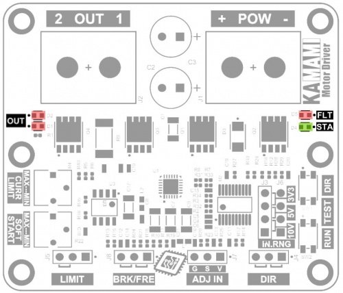
<b>OUT</b> (Output) - | <b>OUT</b> (Output) - The output voltage is signaled using two LEDs marked as OUT on the controller board. Each diode corresponds to one direction of rotation, but in the case of high-power motors, the energy induced in the motor during PWM control will cause both diodes to light up simultaneously. The diodes will glow brighter, the greater the output drive level. | ||
<br><br> | <br><br> | ||
<b>STA</b> (Status) - | <b>STA</b> (Status) - During normal controller operation, the green STA LED lights continuously. When the engine is forced to stop by a signal on the LIMIT connector, the STA LED will glow with short pulses, thus signaling that one of the stop state termination conditions must be met in order to start the engine. | ||
<br><br> | <br><br> | ||
<b>FLT</b> (Fault) - | <b>FLT</b> (Fault) - During normal operation, the red FLT LED is off. Lighting of the diode with short pulses means that the <b>CURRENT LIMIT</b> overload protection is working, i.e. limiting the current supplying the motor. When the FLT LED is lit continuously, the controller is turned off due to overload and/or overheating. | ||
<br><br> | <br><br> | ||
<center> | <center> | ||
| Line 274: | Line 272: | ||
</center> | </center> | ||
===== | ===== Power and load ===== | ||
<center> | <center> | ||
{| class="wikitable" style="width: 1000px;" | {| class="wikitable" style="width: 1000px;" | ||
|- | |- | ||
! style="text-align: center;"| | ! style="text-align: center;"|Connector | ||
! style="text-align: center;"| | ! style="text-align: center;"|Function | ||
|- | |- | ||
| style="text-align: center;"|<b>POW<br>OUT<br></b> | | style="text-align: center;"|<b>POW<br>OUT<br></b> | ||
DG35 screw connector, M3 22...12AWG | |||
| style="text-align: left;"| | | style="text-align: left;"| | ||
* POW – | * POW – connector for connecting power supply | ||
* OUT – | * OUT – connector for connecting a load | ||
|} | |} | ||
</center> | </center> | ||
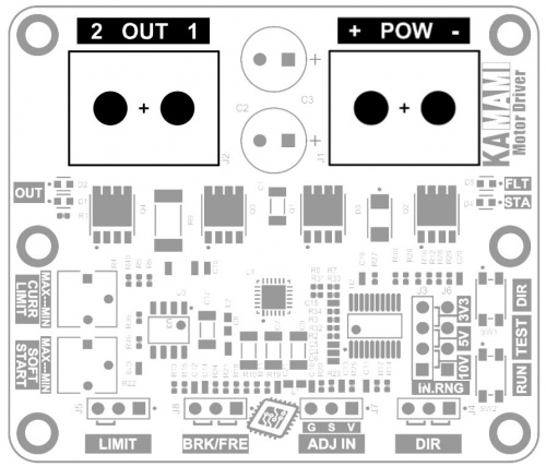
<b>POW</b> - | <b>POW</b> - The supply voltage connected to the POW connector must be in the range of 6...30 V. It is used to power the engine controller and the load connected to its output, e.g. a motor. For high-power loads, a power source with adequate capacity must be provided. The connector is equipped with M3 screws. | ||
<br><br> | <br><br> | ||
<b>OUT</b> - | <b>OUT</b> - Connector enabling connection of a load, e.g. a DC electric motor, etc. The rated voltage of the motor must correspond to the voltage supplying the controller. The rated current of the motor should not exceed 15 A. The connector is equipped with M3 screws. | ||
<br><br> | <br><br> | ||
In the case of high-power loads, ensure that the diameter of the connection cables is large enough and the length of the connection cables is as short as possible. | |||
<br><br> | <br><br> | ||
<center> | <center> | ||
| Line 298: | Line 296: | ||
</center> | </center> | ||
===== | ===== Dimensions ===== | ||
The KAmod Motor Driver board has dimensions of 65x56 mm and a height of approx. 21 mm. The location of the mounting holes is shown in the drawing. | |||
<br><br> | <br><br> | ||
<center> | <center> | ||
[[File:WYMIARY.jpg|none|500px|thumb|center]] | [[File:WYMIARY.jpg|none|500px|thumb|center]] | ||
</center> | </center> | ||
===== | |||
*[https://www.ti.com/lit/ds/symlink/drv8701.pdf | ===== External links ===== | ||
*[https://www.ti.com/lit/ds/symlink/drv8701.pdf DRV8701 data sheet] | |||
Latest revision as of 09:34, 2 November 2024

Description
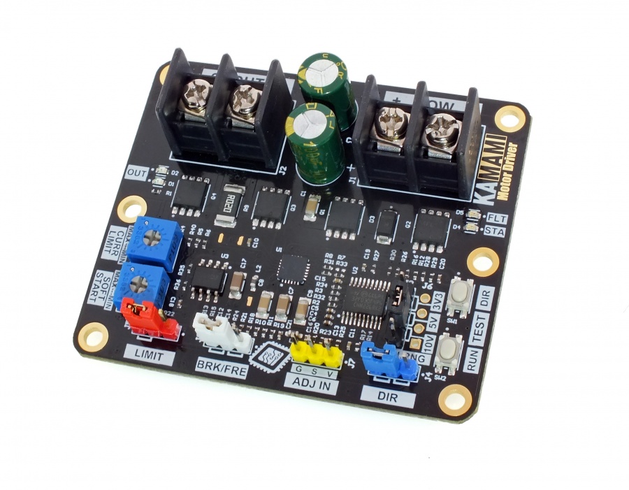
The KAmod Motor Driver is an electric motor controller for DC voltages up to 30 V. It allows the selection of the motor's direction of rotation and the adjustment of its power in the range 0...100%, which in practice is used for speed control. The control signal can be a voltage signal falling within one of 3 ranges: 0...3.3 V, 0...5 V or 0...10 V, or a PWM signal with an amplitude of 3.3 V, 5 V or 10 V. Such signals can be easily obtained from Raspberry, Arduino, Nucleo boards or from a simple potentiometer. The power stage is built with MOSFET transistors connected in an H-bridge arrangement, which ensures high output power and high efficiency of the controller.
Basic features and parameters
- Regulates motor power using PWM method
- Allows motor operation in both directions
- Motor power can be controlled by analogue or digital signal.
- Analogue control signal can be in one of 3 ranges: 0...3.3 V, 0...5 V or 0...10 V
- A digital control signal in the form of a PWM waveform should have a frequency in the range of 200 Hz... 50 kHz and an amplitude of 3.3 V, 5 V or 10 V.
- Separate digital input to control the direction of motor rotation.
- Soft start and soft stop function.
- Stop function with limit sensor signal
- Stop function with or without blocking of the motor shaft
- Output frequency of PW signal
- PWM output signal frequency: 750 Hz.
- Overload protection (output current limitation).
- Protection against overheating
- DC voltage supply in the range 6...30 V
- Maximum continuous motor current: 15 A
- Buttons for quick testing
- LEDs to indicate the operating status of the unit
Standard equipment
| Code | Description |
|---|---|
| KAmod Motor Driver | Assembled and launched module |
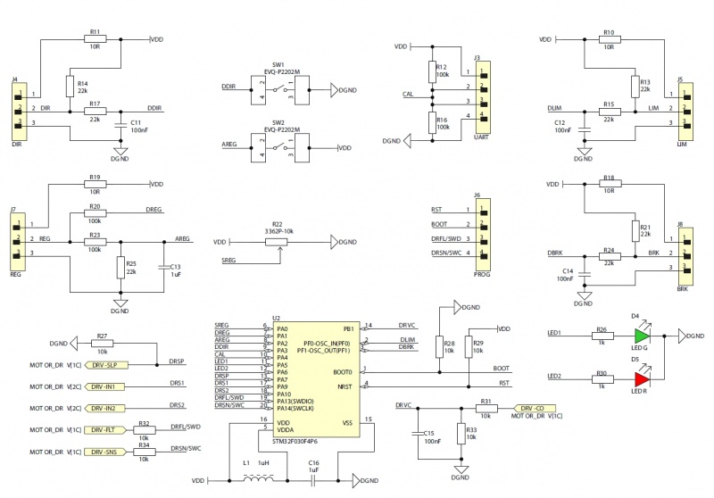
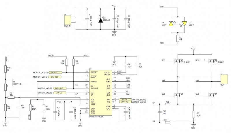
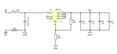
Electrical schematics
Output power control
| Connector | Function |
|---|---|
| ADJ IN
Goldpin pins 3x1, 2,54 mm |
|
The ADJ IN connector pins perform the following functions:
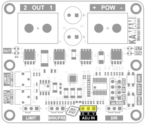
- V (pin 1, right) – 3.3 V voltage output that can be loaded with a current of up to 10 mA;
- S (pin 2, middle) – analog or digital signal input, the maximum input voltage cannot exceed 16V;
- G (pin 3, left) –ground of the system, the ground of the control signal should be connected.
The supplied analog signal must be in one of the 3 control ranges: 0...3.3 V; 0...5 V or 0...10 V. The output power of the motor controller will be proportional to the voltage applied to the S contact and depends on the selected control range. You can connect an ordinary potentiometer to the V, S, G contacts of the connector and thus regulate the output power.
Digital signal - PWM can have a frequency ranging from 200 Hz to 50 kHz, a duty cycle ranging from 0 to 100% and an amplitude of 3.3 V, 5 V or 10 V. The output power of the motor controller will be proportional to the duty cycle of the PWM signal .
The control range for both analog and digital signals is selected using the IN.RNG connector.
Selection of the control signal amplitude range
| Connector | Function |
|---|---|
| IN.RNG
Goldpin pins 4x1, 2.54 mm |
|
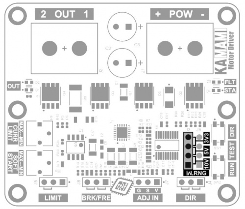
The control signal fed to the ADJ IN connector may come from various systems, development boards and SBC computers. The two most popular standards for the voltage level of digital systems are 3.3 V and 5 V. The analog signal used in home and industrial automation systems is a signal in the range of 0...10 V. In order for the KAmod Motor Driver to work properly with various systems, it must be set the correct voltage range for the control signal. The IN.RNG (input range) connector is used for this purpose.
Setting the jumper in one of 3 positions allows you to select 1 of 3 ranges:
- valve on pins 1-2: voltage range for the control signal is 10 V;
- valve on pins 2-3: voltage range for the control signal is 5 V;
- valve on pins 3-4: voltage range for the control signal is 3.3 V.
The jumper position and corresponding voltage ranges are clearly marked on the motor controller board.
Output polarity control (direction of motor rotation)
| Connector | Function |
|---|---|
| DIR
Goldpin pins 3x1, 2.54 mm |
|
The direction of rotation of a typical DC motor depends on the polarity of the voltage supplying the motor. By reversing the polarity of the voltage, you can reverse the direction of motor rotation. The KAmod Motor Driver allows you to select the direction of motor rotation using the state on the DIR connector.
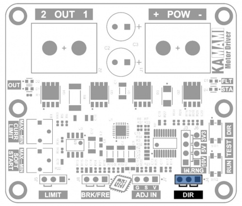
Setting the jumper in one of two positions allows you to select one of two directions - the polarity of the output voltage:
- valve on pins 1-2 (on the right side): there will be a positive potential at the OUT 1 output, and a power supply ground at the OUT 2 output;
- valve on pins 2-3 (on the left): the OUT 1 output will have a power supply ground, and the OUT 2 output will have a positive potential.
The DIR connector pins perform the following functions:
- pin 1 (right) – 3.3 V voltage output, which can be loaded with a current of up to 10 mA;
- pin 2 (middle) – input of a digital signal determining the direction;
- pin 3 (left) – ground of the system, connect the ground of the control signal.
The DIR input is normally pulled up to 3.3V (pull-up). The state will change after applying ground to pin 2 or shorting pins 2-3. Voltage up to 6 V can be supplied to the input.
Forcing the engine to stop
| Connector | Function |
|---|---|
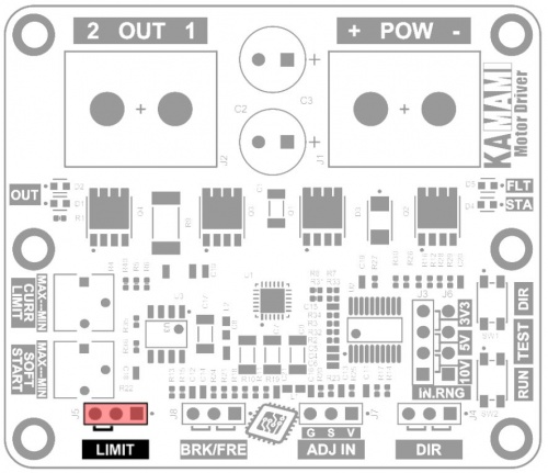
| LIMIT
Goldpin pins 3x1, 2.54 mm |
|
Engine operation can be interrupted at any time. The output power is then set to 0% regardless of the control signal supplied to the ADJ IN input. After stopping using the LIMIT connector, restarting the engine is possible when one of 2 conditions is met:
- the direction of rotation will be changed by changing the state on the DIR connector. The motor will start running in the opposite direction even if the LIMIT signal remains active when the direction is reversed.
- the control signal on the ADJ IN connector will reach zero and the signal on the LIMIT connector will become inactive. After increasing the signal at the ADJ IN connector again, the motor will start running in any direction you set.
The state on the LIMIT connector is:
- active when pins 2-3 (left side) are shorted;
- inactive when pins 1-2 (right side) are shorted, or no pins are shorted.
The LIMIT connector pins perform the following functions:
- pin 1 (right) – 3.3 V voltage output, which can be loaded with a current of up to 10 mA;
- pin 2 (middle) – digital signal input activating the stop function;
- pin 3 (left) – ground of the system, connect the ground of the control signal.
The LIMIT input is normally pulled up to 3.3V (pull-up). The active state will occur after applying ground to pin 2 or shorting pins 2-3. Voltage up to 6 V can be supplied to the input.
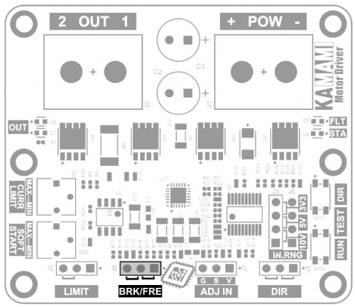
BRK/FRE – Select the stop method
| Connector | Function |
|---|---|
| BRK/FRE
Goldpin pins 3x1, 2.54 mm |
|
Stopping the engine using the LIMIT connector can be done in two ways:
- freely,
- with braking.
The BRK/FRE connector status allows you to select one of these options:
- free stop - shorted pins 1-2 (right side). Power to the motor is disconnected and the motor decelerates to a stop;
- stop with braking - pins 2-3 shorted (on the left). The motor's power is disconnected and its power terminals are shorted to ground, causing the motor to suddenly decelerate.
The activated stop function with braking means that when there is a zero control signal on the ADJ IN connector, the motor is also blocked - its power terminals are shorted to ground, which makes it much more difficult to rotate it using an external force.
Quick test buttons
| Type | Function |
|---|---|
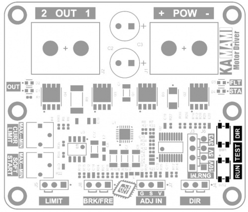
| TEST
Microswitch buttons |
|
The KAmod Motor Driver can be easily tested without applying control signals, using two miniature buttons located on the board:
- TEST RUN – pressing the button sets the output power to 100%, regardless of the signal level on the ADJ IN connector;
- TEST DIR – pressing the button changes the direction of rotation if the DIR connector is not controlled by an external signal.
Potentiometers for adjusting operating parameters
| Type | Function |
|---|---|
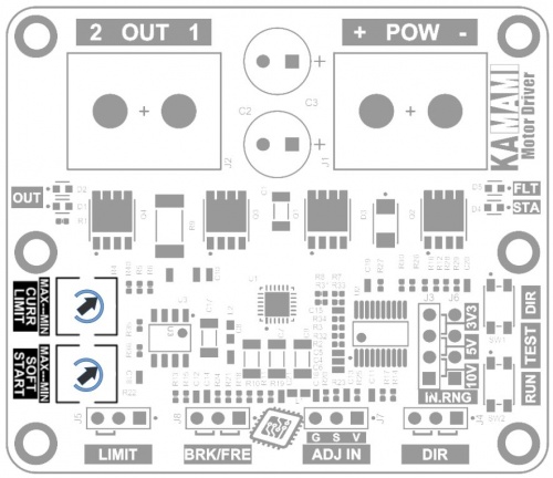
| SOFT START CURR LIMIT Miniature potentiometers |
|
The KAmod Motor Driver implements the SOFT START function, which includes:
- soft start,
- gentle speed increase,
- gentle reduction of speed,
- smooth change of the direction of rotation (with stages of gentle braking, stopping and gentle starting).
The operation of these solutions allows to reduce the load on the power source and limit the mechanical overload of the engine and mechanical elements connected to the engine. The intensity of the above functions is determined by the position of the potentiometer marked SOFT START. In the range from MIN to MAX, the startup time from 0% to 100% is adjustable from 1 to 4 seconds.
The KAmod Motor Driver implements the CURRENT LIMIT overload protection function, which protects the controller and the motor against too high current flow (the function does not guarantee protection against short circuit at the controller output). The current limit level is determined by the position of the potentiometer marked CURR LIMIT. In the range from MIN to MAX, the current value is adjusted from approx. 2 A to approx. 15 A. The limitation operation is indicated by the flashing of the red FLT LED.
Operating status indication
| Type | Function |
|---|---|
| OUT FLT STA LEDs |
|
OUT (Output) - The output voltage is signaled using two LEDs marked as OUT on the controller board. Each diode corresponds to one direction of rotation, but in the case of high-power motors, the energy induced in the motor during PWM control will cause both diodes to light up simultaneously. The diodes will glow brighter, the greater the output drive level.
STA (Status) - During normal controller operation, the green STA LED lights continuously. When the engine is forced to stop by a signal on the LIMIT connector, the STA LED will glow with short pulses, thus signaling that one of the stop state termination conditions must be met in order to start the engine.
FLT (Fault) - During normal operation, the red FLT LED is off. Lighting of the diode with short pulses means that the CURRENT LIMIT overload protection is working, i.e. limiting the current supplying the motor. When the FLT LED is lit continuously, the controller is turned off due to overload and/or overheating.
Power and load
| Connector | Function |
|---|---|
| POW OUT DG35 screw connector, M3 22...12AWG |
|
POW - The supply voltage connected to the POW connector must be in the range of 6...30 V. It is used to power the engine controller and the load connected to its output, e.g. a motor. For high-power loads, a power source with adequate capacity must be provided. The connector is equipped with M3 screws.
OUT - Connector enabling connection of a load, e.g. a DC electric motor, etc. The rated voltage of the motor must correspond to the voltage supplying the controller. The rated current of the motor should not exceed 15 A. The connector is equipped with M3 screws.
In the case of high-power loads, ensure that the diameter of the connection cables is large enough and the length of the connection cables is as short as possible.
Dimensions
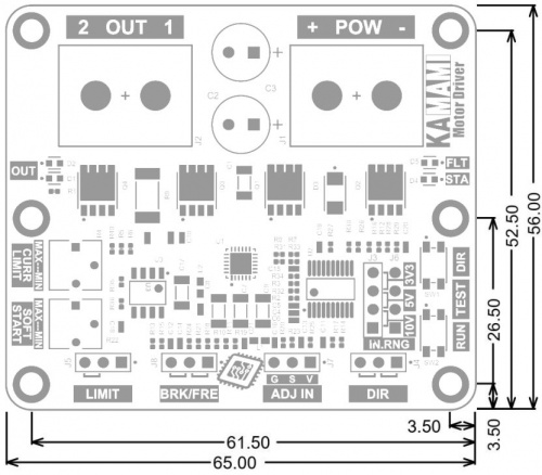
The KAmod Motor Driver board has dimensions of 65x56 mm and a height of approx. 21 mm. The location of the mounting holes is shown in the drawing.
