ZL7AVR: Difference between revisions
From Kamamilabs.com - Wiki
Anna Kubacka (talk | contribs) Created page with "__jzpdf__ ====== Description ====== [https://kamami.com/avr-boards/16860-zl7avr.html ZL7AVR] is a DIP module with ATmega128A microcontroller with 16MHz frequency osscillator...." |
Anna Kubacka (talk | contribs) |
||
| Line 35: | Line 35: | ||
===== Electrical schematic ===== | ===== Electrical schematic ===== | ||
<center> | <center> | ||
[[File:ZL7AVR_schemat. | [[File:ZL7AVR_schemat.jpg|none|800px|thumb|center]] | ||
</center> | </center> | ||
Revision as of 07:37, 30 August 2018

Description
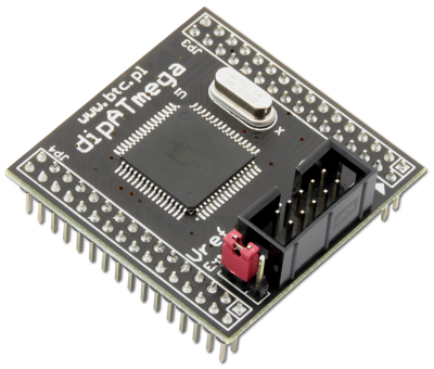
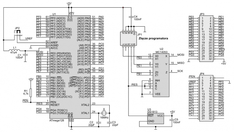
ZL7AVR is a DIP module with ATmega128A microcontroller with 16MHz frequency osscillator. Module is ideal for set ZL8AVR. On board is placed a DS1813 reset system of microcontrollerand automatic switching separator of line ISP (MC14053) for programming.

Basic features and parameters
- Microcontroller ATmega128 from Atmel
- Program memory (ISP): 128kB
- Data memory EEPROM: 4kB
- Data memory SRAM: 4kB
- Clock frequency: 16MHz
- Embedded line separator ISP (with automatic controll)
- Kanda ISP connector for programming (compatibile with i.a. KamPROG)
- Embedded reset signal generator
- Possibility of using external reference voltage source for A/C converter
- I/O lines: 53
- Power supply voltage: 4.5...5.5V/100mA (max.)
Standard equipment
| Code | Description |
|---|---|
| ZL7AVR |
|
Electrical schematic

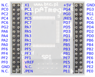
Output description

Output description of module ZL7AVRA
Programming
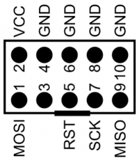
For programming of ZL7AVR can be used any of programmer with ISP connector with support for ATmega128A. Recommended programmer for ZL7AVR is KamPROG.

ISP connector output description (top view)
ADC reference voltage
JP2 jumper allows to choose a reference voltage for analog-to-digital converter of microcontroller. By position1-2 of jumper, on VREF line of microcontroller is 5V and by position 2-3 of jumper (Ext) reference voltage is getting form VREF line of module.