KAmodRPi-Pmod-HAT: Difference between revisions
From Kamamilabs.com - Wiki
| Line 27: | Line 27: | ||
| style="text-align: center;"|<b>KAmodRPi-Pmod-HAT</b> | | style="text-align: center;"|<b>KAmodRPi-Pmod-HAT</b> | ||
| style="text-align: center;"| | | style="text-align: center;"| | ||
* | * Assembled and launched module | ||
* Four spacers with a set of screws for mounting | * Four spacers with a set of screws for mounting | ||
Revision as of 13:04, 18 March 2020

Description
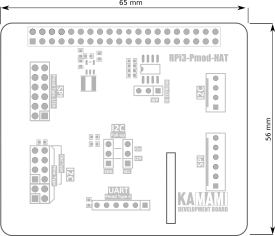
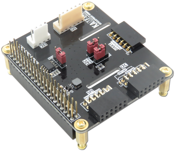
KAmodRPi-Pmod-HAT is a HAT for Raspberry Pi 4B/3B+/3B/2B/B+ minicomputers that allows use of the communication interfaces available on the 40-pin minicomputer connector. The overlay provides connectors in the Pmod standard and in the KAMAMI standard for I2C, SPI and UART interfaces.
Basic parameters
- Expansion module for Raspberry Pi 4B, 3B+, 3B, 2B, B+ minicomputers
- Embedded ID-EEPROM memory
- Connectors for I2C, SPI and UART interfaces
- Pmod connectors
- KAMAMI connectors
- 40-pin through connector compatible with the Raspberry Pi standard
- Embedded jumpers enabling pull-up on I2C bus lines
- Mounting holes with a diameter of 2.5 mm
- Dimensions: 65 mm x 56 mm x 16 mm
Standard equipment
| Code | Description |
|---|---|
| KAmodRPi-Pmod-HAT |
|
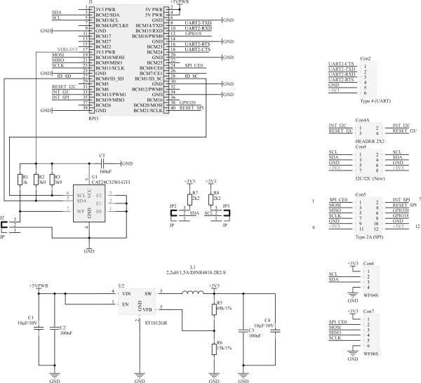
Schematic
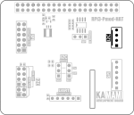
Pin description - I2C KAMAMI standard connector
 |
Pin number | Function |
|---|---|---|
| 1 (VDD_3,3V) | Power supply (max. 3,3 V) | |
| 2 (SCL) | Clock line of the I2C bus | |
| 3 (SDA) | Data line of the I2C bus | |
| 4 (GND) | Ground |
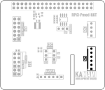
Opis wyprowadzeń – złącze SPI standardu KAMAMI
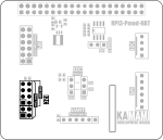
Opis wyprowadzeń – złącze I2C standardu Pmod
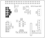
Opis wyprowadzeń – złącze SPI standardu Pmod
Opis wyprowadzeń – złącze UART standardu Pmod
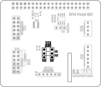
I2C bus lines
The KAmodRPi-Pmod-HAT module is equipped with jumpers that allow the connection of pull-up resistors to the VCC to the I2C bus line. Jumpers allow the independent activation of chin up for SDA and SCL lines.
Write protection of the ID EEPROM memory
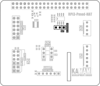
The KAmodRPi-Pmod-HAT module is equipped with a jumper that allows write block to EEPROM memory. Write Protect protects against unwanted attempts to write data to memory.
Dimensions
