KAmodRPI5 REL POW: Difference between revisions
From Kamamilabs.com - Wiki
| Line 313: | Line 313: | ||
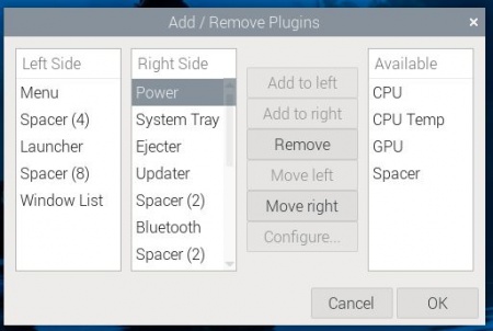
Now you need to find the module '''''Power''' '' and press '''''Remove''''' and confirm with <b>OK</b>. After these actions, the warning will not be displayed. | Now you need to find the module '''''Power''' '' and press '''''Remove''''' and confirm with <b>OK</b>. After these actions, the warning will not be displayed. | ||
===== Links===== *[https://wiki.kamamilabs.com/images/b/b0/XL4015-Xlsemi.pdf Datasheet of the XL4015 system] *[https://wiki.kamamilabs.com /images/c/c8/TLP2348-E-T.pdf Data sheet of the TLP2348 optocoupler] *[https://wiki.kamamilabs.com/images/9/93/HF32F.pdf Data sheet of the HF32F relay] *[https://wiki .kamamilabs.com/images/4/40/KAmodRPI_RelaysPlus.zip CAD Model (STEP)] | ===== Links===== | ||
*[https://wiki.kamamilabs.com/images/b/b0/XL4015-Xlsemi.pdf Datasheet of the XL4015 system] *[https://wiki.kamamilabs.com /images/c/c8/TLP2348-E-T.pdf Data sheet of the TLP2348 optocoupler] *[https://wiki.kamamilabs.com/images/9/93/HF32F.pdf Data sheet of the HF32F relay] *[https://wiki .kamamilabs.com/images/4/40/KAmodRPI_RelaysPlus.zip CAD Model (STEP)] | |||
Revision as of 18:40, 25 October 2024

Description
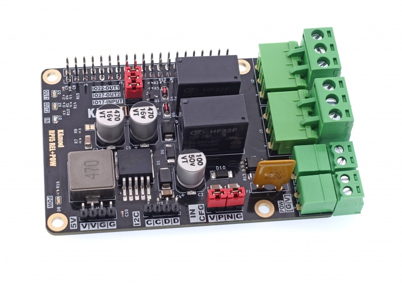
The multifunctional power supply and executive module for Raspberry Pi 5 allows you to power your Raspberry Pi 5 computer from a power source with a voltage of 8 to 32 V. The module also contains two relays with changeover contacts, which allow you to control receivers with a current of up to 3 A. In addition, the board has a digital input circuit with galvanic separation based on an optocoupler. All these functions have been implemented in one compact module, which can be easily connected to the Raspberry Pi 5 and some similar SBCs.
Basic parameters
- Provides power supply with a voltage of 5.1 V with a continuous current of up to 3 A and a short-term current of up to 5 A
- Adapted to input voltage in the range of 8...32 V
- Voltage regulator based on the XL4015 circuit (step-down, 5 A, 180 kHz, 96%)
- Overvoltage, overload and thermal protection
- Two relay outputs with changeover contacts (NC/ON)
- Maximum relay load: 3 A/250 VAC or 3 A/30 VDC
- Digital input with galvanic separation based on an optocoupler
- Digital input parameters: voltage 3.5…32 V (current: 0.5...5 mA)
- Easy installation on Raspberry Pi 5, also with RPi Active Cooler
- Module dimensions 81x56 mm, height approx. 17 mm (and connector under the board approx. 14 mm high)
Standard equipment
| Code | Description |
|---|---|
| KAmod RPI5 REL+POW Mounting kit |
Assembled and launched module A set of screws and spacers for attaching the overlay to the Raspberry board |
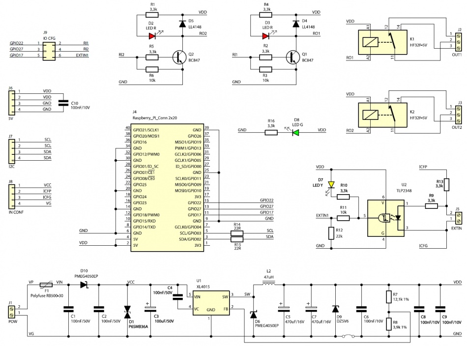
Electrical diagram
Power connector
| Connector | Function |
|---|---|
| POW
Phoenix MC 3.81 mm |
|
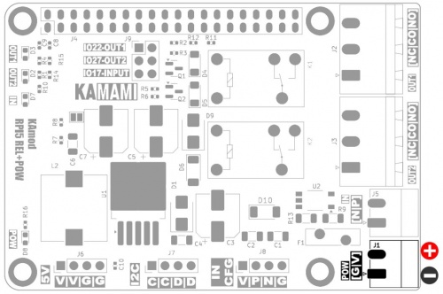
The POW power connector (J1) allows you to connect a direct current (DC) voltage from the range of 8...32 V, from which a voltage of 5.1 V is generated to power the Raspberry Pi. When connecting voltage to the POW connector, pay attention to its correct polarity.
The marking on the board - [G|V] indicates the correct polarity of the power supply:
- G - pin no. 1 is ground, negative power supply pole (GND),
- V - pin no. 2 is the input of the positive power supply pole.
Do not connect a voltage above 34 V. The module contains overvoltage protection, which will disconnect the power supply at a voltage above 34 V.
The connected power source should have adequate power. In order for the module to operate with all parameters (5.1 V/ 5 A), the power of the power supply should not be less than 30 W. Connecting a lower power supply will result in a lower value of the maximum current at the 5 V output.
Relay outputs
| Connector | Function |
|---|---|
| OUT1, OUT2
Phoenix MSTB 5.08 mm |
|
The module contains two HF32F type relays, which allow switching of DC or AC voltage circuits with the following parameters:
- DC – maximum 3 A and 30 V,
- AC – maximum 3 A and 250 V.
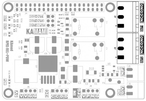
The relays contain changeover contacts, connected to OUT1 (J2) and OUT2 (J3) connectors, in accordance with the [NC|CO|NO] markings on the PCB:
- NO – normally open contact with common contact (Normally Open),
- NC – normally closed contact with common contact (Normally Close),
- CO – common contact (Common).
Input with opto-isolation
| Connector | Function |
|---|---|
| IN
Phoenix MC 3.81 mm |
|
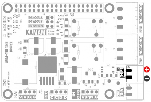
The IN connector (J5) is connected to a TLP2348 digital optocoupler diode. The optocoupler provides galvanic isolation of the IN input, and the built-in Schmitt trigger eliminates many signal interferences. The active state at the optocoupler output is the logical state "0" (L). The maximum frequency of the input signal is approx. 1 MHz.
The signal at the IN input must be a DC voltage in the range of 3.5...32
V connected according to the polarity described on the board [N|P]:
- N - contact no. 1 is the negative pole of the control voltage connected to the cathode of the optocoupler diode,
- P - contact no. 2 is the positive pole of the control voltage connected to the anode of the optocoupler diode.
Power output 5 V
| Connector | Function |
|---|---|
| 5V
Goldpin 1x4, 2.54 mm |
|
The KAmodRPI5 REL+POW module contains a switching stabilizer based on the XL4015 system, which provides a stabilized voltage of 5.1 V ±2% at the output. The maximum total continuous load can be 3 A, while the short-term load can be up to 5 A, if the power of the source powering the module allows it.
The operating time with a load of up to 5 A depends on the efficiency of heat dissipation emitted from the module and can range from a dozen or so seconds to a dozen or so minutes.
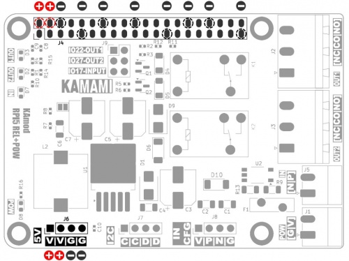
The 5.1 V power output is connected to the connector marked 5V (J6) and to the appropriate GPIO connector pins – as shown in the figure below:
I2C connector
| Connector | Function |
|---|---|
| I2C
Goldpin 1x4, 2.54 mm |
|
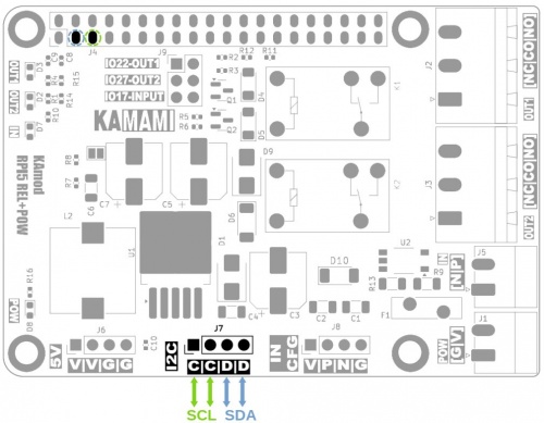
The KAmod RPI5 REL+POW module contains an additional connector marked as I2C (J7), on which the SCL and SDA signals of the I2C interface are derived. The I2C interface is available on the GPIO connector of the Raspberry Pi 5 board:
- pin no. 3 – SDA, GPIO02,
- pin no. 5 – SCL, GPIO03.
Signals from the GPIO connector are connected to the I2C connector via 22 Ω resistors and do not contain pull-up resistors.
Optocoupler configuration connector
| Connector | Function |
|---|---|
| IN CFG
Goldpin 1x4, 2.54 mm |
|
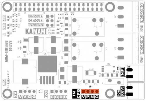
The optocoupler input (optocoupler diode) is connected to the IN connector terminals (J5). By applying an independent voltage to the IN connector, we force the active state at the optocoupler output. The IN input can also be activated by voltage from the POW connector. The pins marked on the board as IN CFG allow you to connect the power supply to one or both inputs of the IN connector and thus obtain different ways of activating the input:
- no jumpers on the IN CFG pins - optocoupler activated by voltage at the IN input;
- jumper on the V-P pins - optocoupler anode (P) connected to the positive power supply contact (V) - the IN input will be activated by shorting the N contact to the power supply ground (G);
- jumper on pins N-G – optocoupler cathode (N) connected to negative power supply contact (G) - IN input will be activated by shorting contact P to plus power supply (V);
- jumpers on pins V-P and N-G – optocoupler anode and cathode connected to POW power supply via 3.3 kΩ resistor on positive power supply line. IN input is in active state, only shorting on IN input (P-N contacts) turns off optocoupler – similarly as in alarm circuits.
RPi standard GPIO connector
| Connector | Function |
|---|---|
| GPIO
Goldpin 2x20, 2.54 mm |
|
The GPIO connector (J4) is compatible with the Raspberry Pi standard. The relay control signals are provided to the pins:
- pin 15 – GPIO22 – OUT1,
- pin 13 – GPIO27 – OUT2.
Setting a high logical state ("1") switches on the given relay.
The signal from the IN input is fed to pin 11: GPIO17 - INPUT. It should be remembered that the active state, corresponding to the optocoupler control, is a low logical state ("0").
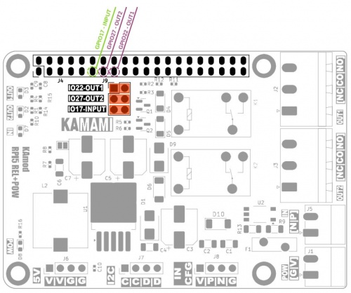
The control signals pass through the J9 pins. If the appropriate pairs are shorted – 5 000 / 5 000
as in the figure below (1-2, 3-4, 5-6) the signals go to the GPIO17, GPIO22, GPIO27 pins. To disconnect the control signals or connect them to other GPIO connector ports, remove the appropriate jumpers from J9 pins and connect pins 2, 4, 6 (on the right) to other ports on the GPIO connector.
Signaling lights
| Indicator | Function |
|---|---|
|
OUT1 |
|
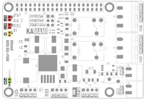
There are 4 miniature LED indicators on the KAmod RPI5 REL+POW module board:
- OUT1 and OUT2 - indicate that the OUT1 and OUT2 output relays are switched on,
- IN - indicates the active state at IN input, i.e. state "0" on the GPIO17 port,
- POW - indicates the presence of 5 V power supply voltage.
Dimensions
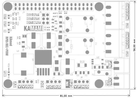
The dimensions of the KAmod RPI5 REL+POW module are 81x56 mm. The maximum height (relays) is approx. 17 mm. On the bottom of the board there is a connector adapted to the Raspberry Pi GPIO with a height of approx. 14 mm.
The module board should be additionally stiffened with sleeves and screws so that the soldering points on the bottom of the board do not short-circuit with the metal housings of the USB and Ethernet connectors of the Raspberry Pi 5 board. The arrangement of the mounting holes is in accordance with the Raspberry Pi standard.
Test script
You can check the operation of the module's input and outputs by running a simple script written in Python. The content of the script is below, it is not complicated and does not require a detailed discussion. Running the script will cause cyclic switching of one relay, and the other will be controlled via the IN input. To end the operation, press the Ctrl + C keys.
Test script code:
import gpiod

from time import *


OUTPIN1 = 22

OUTPIN2 = 27

INPUTPIN = 17
chip = gpiod.Chip('gpiochip4')

out1_line = chip.get_line(OUTPIN1)

out2_line = chip.get_line(OUTPIN2)

input_line = chip.get_line(INPUTPIN)
out1_line.request(consumer='REL1', type=gpiod.LINE_REQ_DIR_OUT)

out2_line.request(consumer='REL2', type=gpiod.LINE_REQ_DIR_OUT)

input_line.request(consumer='>INPUT', type=gpiod.LINE_REQ_DIR_IN)
i =  0

step = 0
print("Out2 - tick/tack; Out1 - set from input; Ctrl + c to exit")
while True:
- i = i + 1
- if i > 10:
- i = 0
- if step > 0:
- step = 0
- out1_line.set_value(0)
- else:
- step = 1
- out1_line.set_value(1)
- if input_line.get_value():
- out2_line.set_value(0)
- else:
- out2_line.set_value(1)
- sleep(0.1)
Warnings generated by the system
The Raspberry Pi 5 computer is equipped with an advanced power management system, the so-called PMIC - Power Management IC. It monitors the power parameters even before the main processor is started and the system starts to boot.
The KAmod RPI5 REL+POW module contains a switching voltage regulator equipped with a number of protections, including: current limitation, which causes the voltage at the output to gradually increase from 0 V to 5.1 V when the power supply is connected to the module. This transient state lasts only a few dozen milliseconds but is incorrectly interpreted by the PMIC system as „low power event" - a situation in which the supply voltage is too low. This is accompanied by a message displayed immediately after starting the Raspberry Pi system desktop:
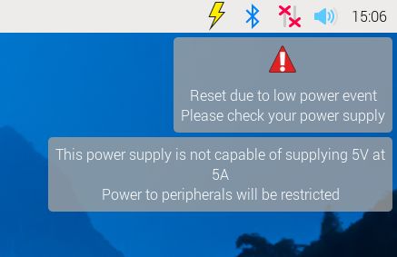
The KAmod RPI5 REL+POW module provides a stable voltage that is more than enough to power the Raspberry Pi 5 computer and many types of attached peripherals. You can verify this by turning off the computer with the command “Shutdown”, and turning it on using the button (without disconnecting the power cable of the KAmod RPI5 REL+POW module). In such a scenario, the warning is not displayed with low supply voltage, because it is completely stable.
The low voltage warning can be disabled. To do this, right-click on the top bar and then select Add/Remove Plugins….
Now you need to find the module Power and press Remove and confirm with OK. After these actions, the warning will not be displayed.

