Kamod BluePill: Difference between revisions
From Kamamilabs.com - Wiki
| Line 230: | Line 230: | ||
The microswitch is connected to port PA0, pressing it forces the state to be low on this port. The button is connected via a 1k resistor, so there is no possibility of damaging port PA0 configured as an output. | The microswitch is connected to port PA0, pressing it forces the state to be low on this port. The button is connected via a 1k resistor, so there is no possibility of damaging port PA0 configured as an output. | ||
<center> [[File:Kamod BluePill LED.jpg|none|750px|thumb|center]] </center> ===== GPIO connectors ===== <center> {| class="wikitable" style="width: 1000px;" | <center> [[File:Kamod BluePill LED.jpg|none|750px|thumb|center]] </center> | ||
===== GPIO connectors ===== | |||
<center> {| class="wikitable" style="width: 1000px;" | |||
|- ! style="text-align: center;"|Connector ! style="text-align: center;"|Function |- | style="text-align: center;"|<b>J1, J2</b> | style="text-align: left;"| | |- ! style="text-align: center;"|Connector ! style="text-align: center;"|Function |- | style="text-align: center;"|<b>J1, J2</b> | style="text-align: left;"| | ||
* 20-pin connectors with a 2.54 mm pitch, to which the microcontroller's GPIO ports and 5 V and 3.3 V power supply are connected | * 20-pin connectors with a 2.54 mm pitch, to which the microcontroller's GPIO ports and 5 V and 3.3 V power supply are connected | ||
Revision as of 16:15, 26 October 2024

Description
Kamod BluePill+
Evaluation board with STM32F103C8T6 microcontroller, compatible with BluePill
The Kamod BluePill+ evaluation board contains the STM32F103C8T6 microcontroller and the components necessary to run and program it. The board is pin-compatible with the BluePill project, but has a number of improvements, including: new PCB design, USB-C connector with ESD protection, or improved power supply circuit. It can be programmed with Arduino IDE, because the system memory contains a suitable bootloader.
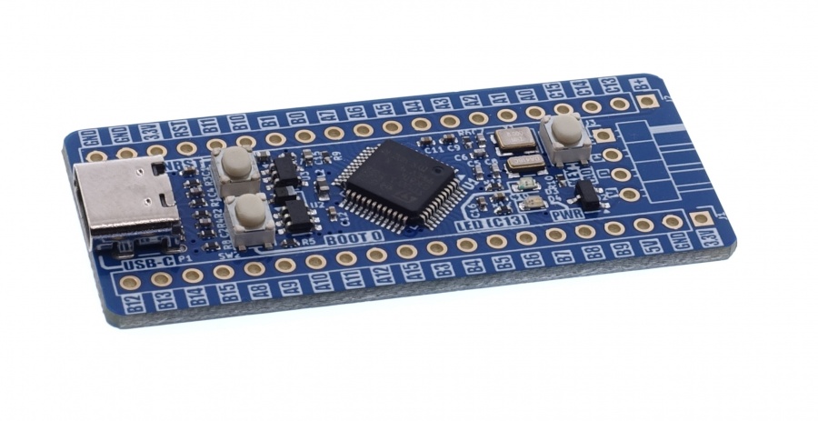
Basic features and parameters
- STM32F103C8T6 microcontroller: 64 kB Flash, 20 kB RAM, 72 MHz, 2 x 12-bit ADC, 4 timers, 2 x I2C, 2 x SPI, 3 x UART, CAN, USB, RTC
- USB-C connector, which serves as a power connector, USB communication interface and allows for microcontroller programming
- elements filtering interference and overvoltages on USB interface lines
- 32 GPIO pins and 5 V and 3.3 V power lines available on standard 2.54 mm pitch connectors
- maximum load on the 5 V line is 500 mA, while for the 3.3 V line it is 200 mA
- precise resonator clocking the microcontroller and an independent resonator for the RTC module
- possibility of connecting a battery to support the RTC module
- SWD programming/debugging interface connector
- possibility of programming via STM32CubeIDE and Arduino IDE
- board dimensions: 53.5x23 mm, height approx. 7 mm (without soldered goldpins)
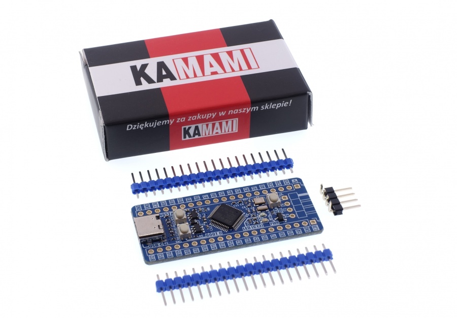
Standard equipment
| Code | Description |
|---|---|
| Kamod BluePill+ |
|
Electrical diagram
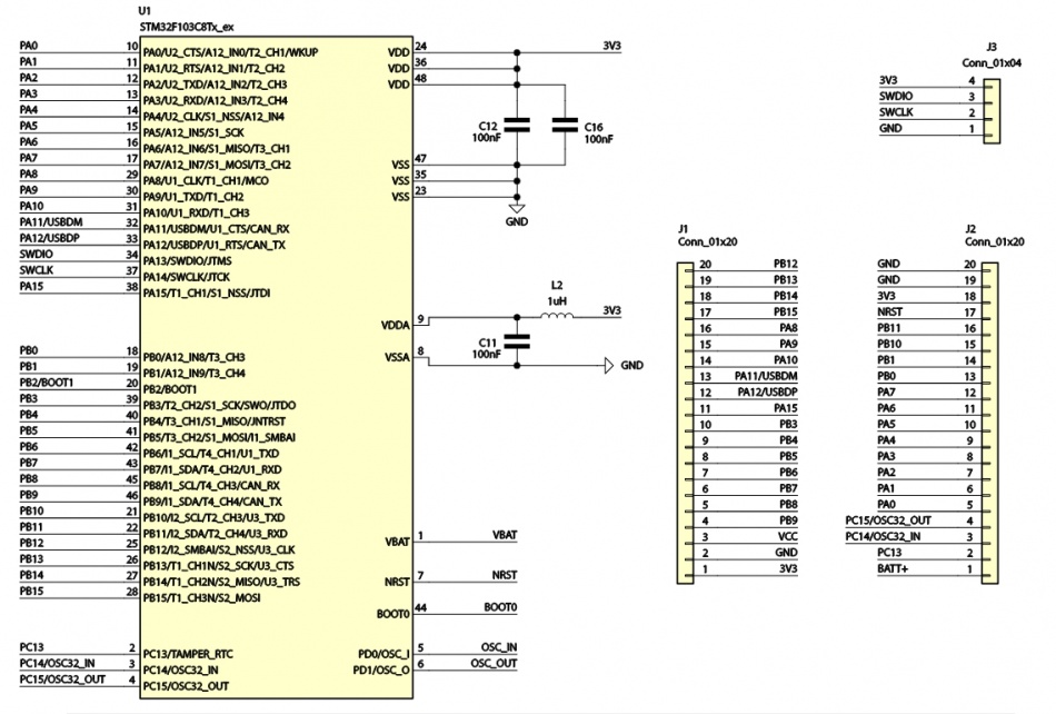
- Microcontroller and GPIO and SWD connectors
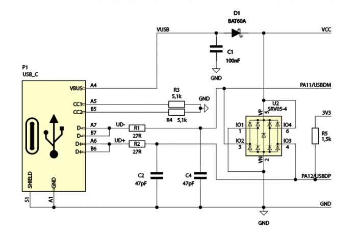
- USB interface
- Power supply circuit

- Microcontroller clock speed
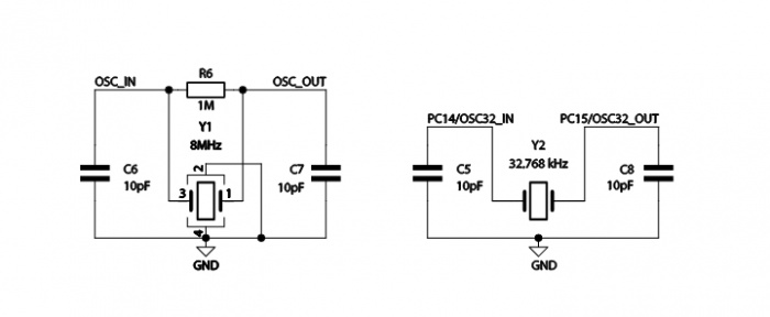
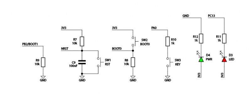
- Additional elements
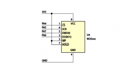
- External memory
Power
| Connector | Function |
|---|---|
| USB-C
J1, J2 |
|
The Kamod BluePill+ evaluation board can be powered in two ways:
- via the appropriate contacts of J1 and J2 connectors,
- via the USB-C connector.
A power source with a voltage in the range of 4.5...5.5 V and an efficiency of min. 100 mA should be connected to the contacts marked ' 5V (plus) and GND (minus) on connectors J1 and/or J2. Then, on the contact marked 3.3V, a stabilized voltage of 3.3 V is available, which also powers the microcontroller. The presence of 3.3 V is indicated by the LED marked PWR' lighting up.
A standard USB power source with a capacity of at least 100 mA should be connected to the USB-C connector. Then, on the 5V contact of connector J1, a voltage of close to 5 V is available (relative to the ground marked GND). A small voltage drop (approx. 0.5 V) occurs on the Schottky diode, which allows current to flow in the direction from the USB-C connector to the board, but blocks current flow in the opposite direction - to the USB-C connector. Thanks to this, you can safely connect power in various configurations - USB and/or J1, J2 contacts.
There is a contact marked B+' on the J2 connector. Together with the ground GND this is the power input from the battery supporting the RTC clock (integrated with the microcontroller). The backup battery voltage should be in the range of 1.8...3.6 V. Detailed information on the operation of the RTC module can be found in the documentation for the STM32F103C8T6 microcontroller.
USB interface
| Connector | Ffunction |
|---|---|
| USB-C |
|
The USB-C connector is an easy way to provide power to the Kamod BluePill+ board. In addition, the STM32F103C8T6 microcontroller has an integrated USB 2.0 FS interface controller, which can be used for communication, e.g. in VCP (Virtual COM Port) or CDC (Communication Device Class) mode.
The board has been configured in such a way that it allows the interface to operate in Peripheral mode, it is not prepared to work in Host mode. The board also contains elements that filter possible interference and overvoltages on the USB interface lines, which ensure its stable operation.
Additional functionality of the USB-C connector is the ability to program the microcontroller's Flash memory. This requires an appropriate bootloader, which is loaded into the Kamod BluePill+ module microcontroller along with the test program.
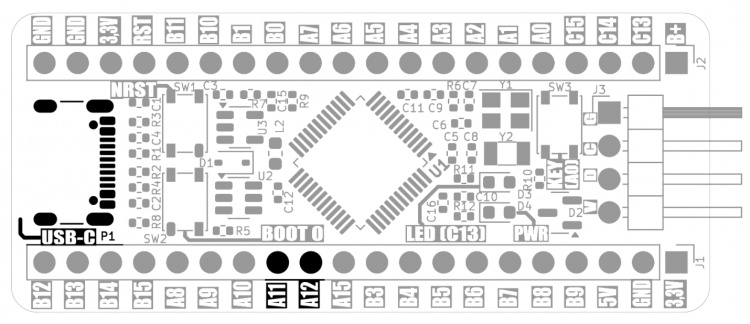
The USB interface lines (DP and DM) are also GPIO ports PA12 and PA11 of the microcontroller. If we use USB, the contacts marked A12 and A11 cannot perform any other function - they must remain unconnected.
SWD programming/debugging interface
| Connector | Function |
|---|---|
| J3 |
|
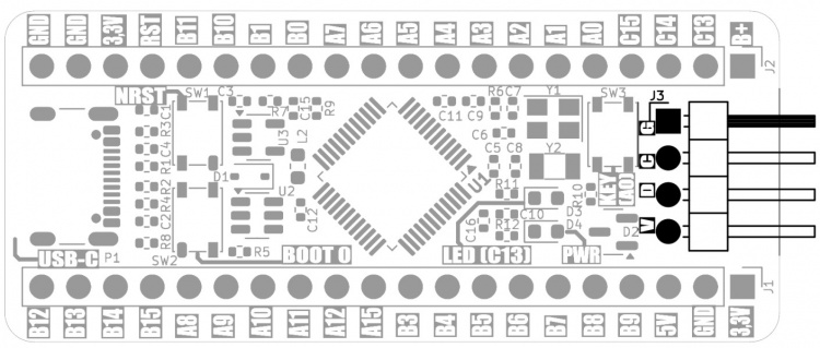
The SWD (Single Wire Debug) interface allows for programming the microcontroller's Flash memory and tracking the program's operation (debugging). Requires the connection of an external programmer/debugger, e.g. STLINK-V2 or STLINK-V3MINIE.
The SWD interface has been led out to the J3 pin connector. The signals are described as follows:
- G – system ground,
- C – SWCLK clock signal,
- D – SWDIO data signal,
- V – 3.3 V power line.
The signals should be connected to the same signals on the programmer/debugger connector. Sometimes SWCLK is also marked as TCK, while SWDIO is also marked as TMS. The programmer does not supply power to the Kamod BluePill+ board, the power should be connected to the USB-C connector or J1/J2 pins.
Microcontroller programming
| Component | Function |
|---|---|
|
SW1 – NRST |
|
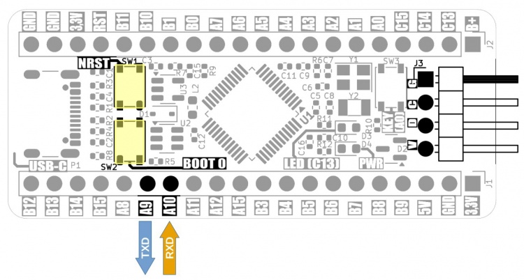
A special area of the microcontroller's memory contains software that allows programming its program memory - this is the so-called bootloader prepared by the microcontroller manufacturer. To start the bootloader, perform the following sequence of actions, with the board's power supply connected:
- Press and hold the NRTS button
- Press and hold the BOOT 0 button while holding the NRST button
- Release the NRTS button while holding the BOOT 0 button
- Release the BOOT 0 button
Starting the bootloader activates two programming interfaces:
- SWD, which was described in the previous chapter and allows programming the microcontroller using a programmer/debugger, e.g. STLINK-V2 or STLINK-V3MINIE.
- UART, which allows you to use a regular USB-UART converter as a programmer, e.g. KAmod USB-UART-mini. Then you need to connect the UART interface lines to the A9 and A10 pins, where:
- A9 – the TXD output of the microcontroller should be connected to the RXD input of the USB-UART converter,
- A10 – the RXD input of the microcontroller should be connected to the TXD output of the USB-UART converter.
Now you can program the microcontroller via SWD or UART using the STM32CubeProgrammer, which is available on the official STMicroelectronics website: https://www.st.com/en/development-tools/stm32cubeprog.html
The Kamod BluePill+ board also allows you to program the microcontroller via the USB interface using the Arduino IDE. This is possible because, along with the test program, an additional bootloader is placed in the program memory for communication and programming in the Arduino environment.duino.Then you should:
- add the following address to the sources of the board manager (Preferences) in the Arduino IDE:https://github.com/stm32duino/BoardManagerFiles/raw/main/package_stmicroelectronics_index.json
- via the board manager (Boards Manager) install the package "STM32 MCU based boards"
- install STM32CubeProgrammer (https://www.st.com/en/development-tools/stm32cubeprog.html)
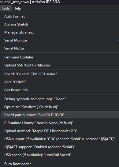
Then, after creating a new sketch, in the Tools tab:
- select the board: BluePill F103C8,
- set the Upload method to: Maple DFU Bootloader 2.0,
- USB support should be set to: CDC (generic Serial),
- U(S)ART support should be set to: Enabled (generic Serial),
- select STM Serial communication port (COMxx).

Additional elements – LED and button
| Component | Function |
|---|---|
|
D3 – LED (C13) |
|
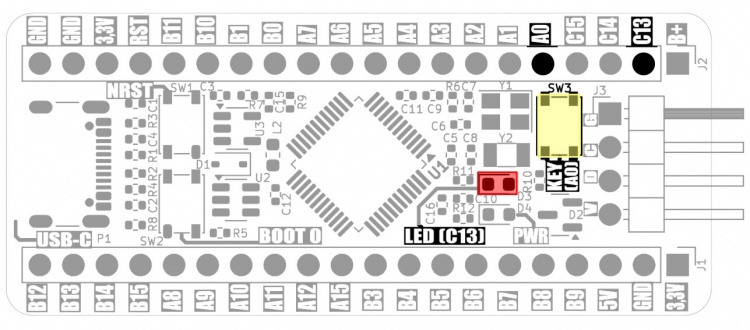
The Kamod BluePill+ board contains additional elements – LED and microswitch, which can be used in the target application.
The LED is connected to port PC13, it lights up when the state is low.
The microswitch is connected to port PA0, pressing it forces the state to be low on this port. The button is connected via a 1k resistor, so there is no possibility of damaging port PA0 configured as an output.
GPIO connectors
|- ! style="text-align: center;"|Connector ! style="text-align: center;"|Function |- | style="text-align: center;"|J1, J2 | style="text-align: left;"|
- 20-pin connectors with a 2.54 mm pitch, to which the microcontroller's GPIO ports and 5 V and 3.3 V power supply are connected
|}
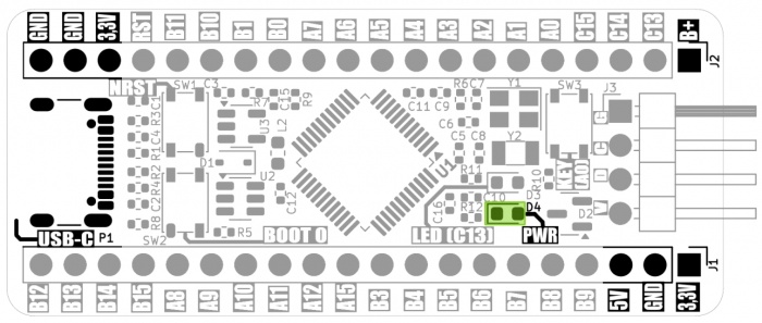
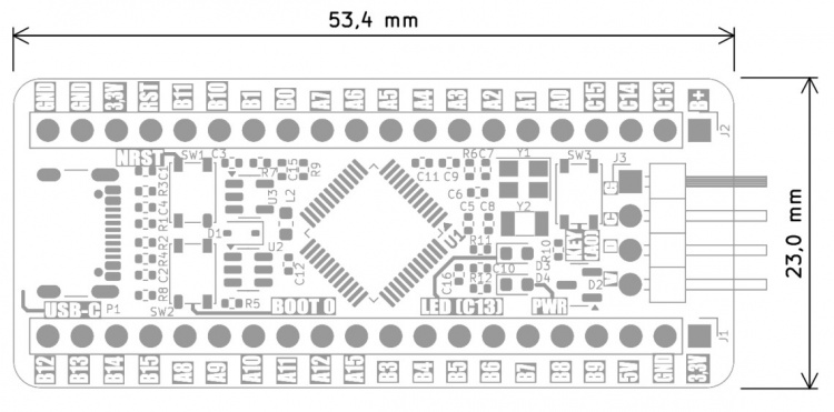
GPIO connectors J1 and J2 contain 20 pins each, to which the 5 V, 3.3 V power supply lines, GND ground and the GPIO pins of the microcontroller module are connected. The exact description of the pins and their additional functions are shown in the drawing and table below:

Dimensions
The dimensions of the Kamod BluePill+ board are 53.5x23 mm, and the height is approx. 7 mm (without soldered goldpins).
Test program
The simplified code of the test program is below, it can be compiled in the Arduino environment.
 #include <STM32RTC.h>

 < font color="#5e6d03">#define LED_PIN   PC13
 #define SW_PIN    PA0

 int message_period = 0;
 int config_state = 0;
 int ports_state = 0;
 int pindex = 0;

 STM32RTC& rtc = STM32RTC::getInstance();

 void setup() {  Serial .begin(115200);  pinMode(<fontcolor="#000000">LED_PIN, OUTPUT) ;  pinMode(SW_PIN, INPUT_PULLUP) ;
rtc.begin(); /& #47; initialize RTC 24H format } // the loop function runs over and over again forever
void loop() { / ;/digitalWrite(LED_PIN, HIGH); if (digitalRead(SW_PIN) = = HIGH){   ; if ((ports_state&4) > 0){ digitalWrite(LED_PIN, < font color="#00979c">HIGH);
} else {
digitalWrite(LED_PIN</ font>, LOW);
} if ( config_state > 0){ IO2input< font color="#000000">(); config_state = 0; } } else { if ((ports_state&1< /font>) > 0){
digitalWrite(LED_PIN</ font>, HIGH);
} else {
digitalWrite(LED_PIN</ font>, LOW);
}
if (config_state == 0) { IO2output(); config_state = 1; }</font