KAmodL3GD20: Difference between revisions
From Kamamilabs.com - Wiki
m Text replacement - "__jzpdf__" to "__jzXpdf__" Tag: Reverted |
No edit summary Tag: Manual revert |
||
| Line 1: | Line 1: | ||
__jzpdf__ | |||
====== Opis ====== | ====== Opis ====== | ||
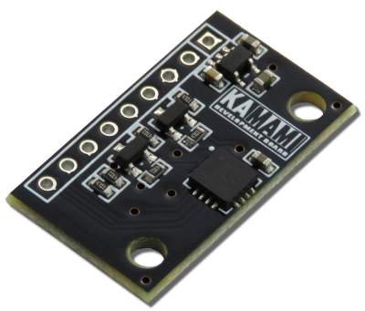
[https://kamami.pl/kamod-kamami/557724-kamodl3gd20-modul-zyroskopu-mems-z-ukladem-l3gd20-firmy-stmicroelectronics.html KAmodL3GD20] is a module with MEMS chip L3GD20 type. It allows to make measurement of angle velocity in range ±250 / ±500 / ±2000 angle per second. Module can be used for measurement of the object inclination and also as complement for magnetometer or accelerometer (e.g. KAmodLSM303) in precision measurement device of physical values. Communication with the module is realize by I2C or SPI interface. | [https://kamami.pl/kamod-kamami/557724-kamodl3gd20-modul-zyroskopu-mems-z-ukladem-l3gd20-firmy-stmicroelectronics.html KAmodL3GD20] is a module with MEMS chip L3GD20 type. It allows to make measurement of angle velocity in range ±250 / ±500 / ±2000 angle per second. Module can be used for measurement of the object inclination and also as complement for magnetometer or accelerometer (e.g. KAmodLSM303) in precision measurement device of physical values. Communication with the module is realize by I2C or SPI interface. | ||
Revision as of 17:00, 1 November 2024

Opis
KAmodL3GD20 is a module with MEMS chip L3GD20 type. It allows to make measurement of angle velocity in range ±250 / ±500 / ±2000 angle per second. Module can be used for measurement of the object inclination and also as complement for magnetometer or accelerometer (e.g. KAmodLSM303) in precision measurement device of physical values. Communication with the module is realize by I2C or SPI interface.

Basic features and parameters
- L3GD20 chip (MEMS gyroscope) from STMicroelectronics
- Measurement range of gyroscope: range ±250 / ±500 / ±2000 dps
- Power supply voltage: 2.5V - 5.5V
- Sleep mode and low power mode
- Communication interface: SPI / I2C
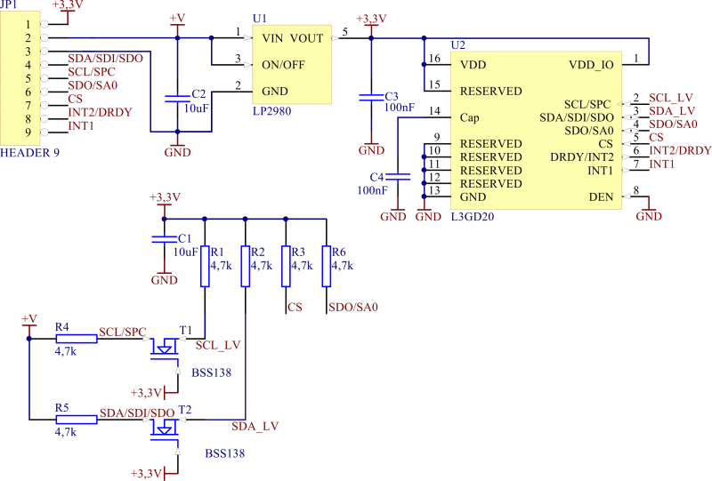
- Embedded voltage regulator and logic level translator (SDA and SCL lines)
- Interrupt line INT1 on connector
- Interrupt FIFO (INT2) line on connector and data ready output (DRDY)
- Place for soldering of pin header
- Mounting holes 3mm
- Module size (without connector): 27mm x 15mm x 3mm
Standard equipment
| Code | Description |
|---|---|
| KAmodL3GD20 |
|
Electrical schematic

