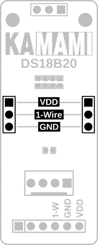
KAmodDS18B20: Difference between revisions
From Kamamilabs.com - Wiki
Removed redirect to KAmodDS18B20 (PL) Tag: Removed redirect |
|||
| Line 1: | Line 1: | ||
__jzpdf__ | __jzpdf__ | ||
====== Description ====== | ====== Description ====== | ||
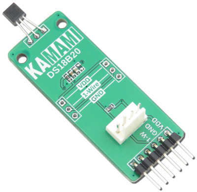
[https://kamami.pl/ | [https://kamami.pl/en/temperature-sensors/572557-kamodds18b20-module-with-ds18b20-temperature-sensor-from-dallas-5906623432684.html KAmodDS18B20] is a module with a DS18B20 temperature sensor from Dallas Semiconductor. The board is equipped with a goldpin connector and a KAMAMI connector, allowing for easy connection of the module to development kits. Thanks to its small dimensions, the product can be used in many development projects. | ||
<center> | <center> | ||
Revision as of 16:34, 1 November 2024

Description
KAmodDS18B20 is a module with a DS18B20 temperature sensor from Dallas Semiconductor. The board is equipped with a goldpin connector and a KAMAMI connector, allowing for easy connection of the module to development kits. Thanks to its small dimensions, the product can be used in many development projects.
Basic features and parameters
- DS18B20 system by Dallas Semiconductor
- Temperature measurement in the range of -55°C ... +125°C
- Temperature measurement accuracy: ±0.5°C in the range of -10°C ... +85°C
- Configurable resolution in the range of 9-12 bits
- The systems have a unique, 64-bit serial number
- Module supply voltage range: 3.0 V - 5.5 V
- 1-Wire bus
- Ability to work in parasitic configuration (parasite power)
- Solder pads allowing for soldering additional sensors
- Connector compliant with the KAMAMI standard
- Holes 2.5 mm diameter mounting
- Dimensions: 72.2 mm x 20.3 mm x 10 mm
Standard equipment
| Code | Description |
|---|---|
| KAmodDS18B20 |
|
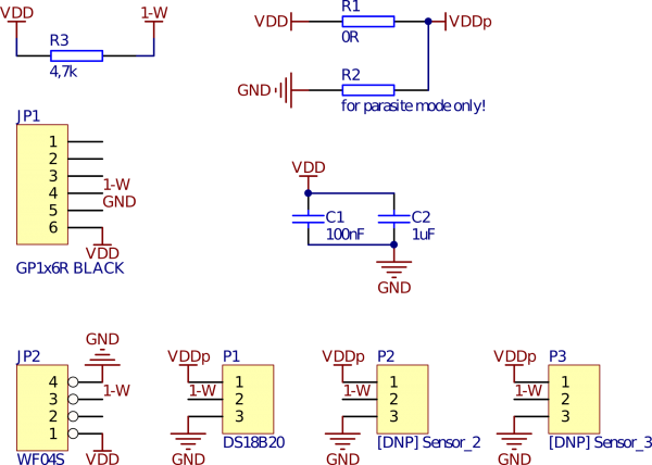
Electrical diagram
Pinout description - goldpin connector
| JP1 (male connector) | Function | |
|---|---|---|
| VDD | Module power supply (max. 5.5 V) | |
| GND | ||
| 1-W | 1-Wire bus line |
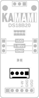
Pinout description - KAMAMI standard connector
 |
Pin number | Function |
|---|---|---|
| 1 (VDD) | Module power supply (max. 5.5 V) | |
| 2 (NC) | Line not used | |
| 3 (1-Wire) | 1-Wire bus data line | |
| 4 (GND) | Power supply ground |
Parasitic power supply mode
The KAmodDS18B20 module allows the sensor to operate in parasitic power supply mode. The module is equipped with a soldered jumper (marked with the letter A in the drawing below), which, when resoldered to position (B), configures the DS18B20 sensor to work in parasitic mode.
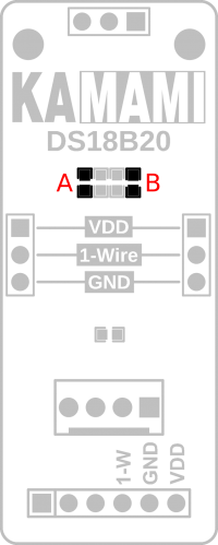
| Note!
In parasitic power supply mode, do not apply voltage to the VDD lines. The pull-up resistor on the board is not active in parasitic mode; pulling up the 1-Wire line should be done on the bus control side, according to the protocol/sensor documentation. |
|---|
Cooperation of multiple sensors
The KAmodDS18B20 module is equipped with through soldering pads, which allow for soldering additional sensors or wires with sensors. Pay special attention to the signal descriptions presented on the module laminate.
