ZL27ARM: Difference between revisions
From Kamamilabs.com - Wiki
Anna Kubacka (talk | contribs) No edit summary |
|||
| Line 6: | Line 6: | ||
[[File:zl27arm.jpg|none|400px|thumb|center]] | [[File:zl27arm.jpg|none|400px|thumb|center]] | ||
</center> | </center> | ||
===== Features ===== | ===== Features ===== | ||
Revision as of 09:34, 24 September 2020

Description
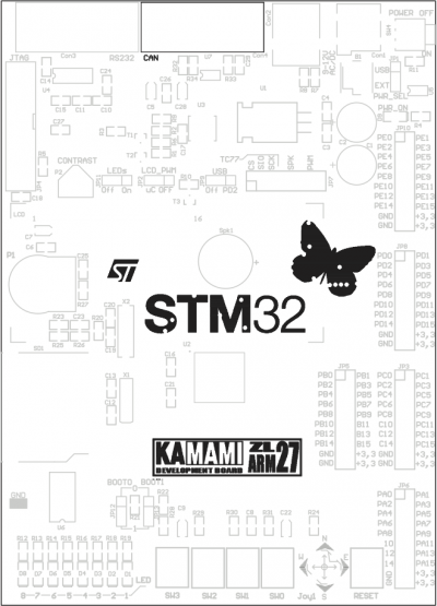
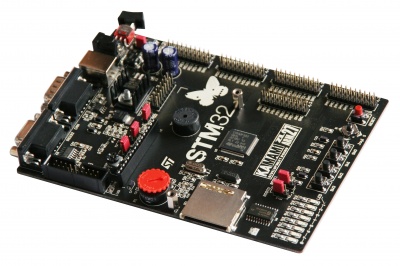
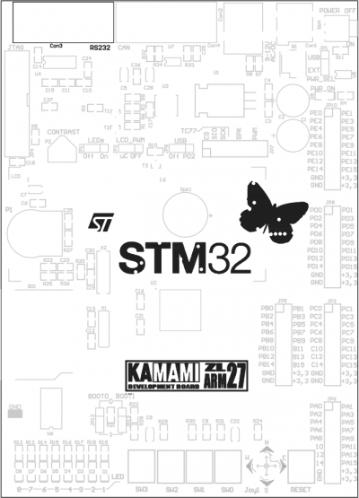
ZL27ARM is versatile evaluation board for STM32F103 microcontrollers. It is equipped with many peripherals (CAN, USB, digital thermometer). It can be used as development board or in educational purposes.
Features
- STM32F103VBT6 microcontroller in LQFP100 package (128kB Flash, 20kB SRAM, 2×SPI, 2×I2C, 3×UART, USB, CAN, ADC)
- Two crystal resonators (8MHz, 32.768kHz)
- 4-switch keyboard
- 5-position joystick
- 8LEDs
- Five 16-bit GPIO ports
- Connector for 2×16 alphanumeric LCD (for example LCD1602)
- LCD backlight with brighness control (PWM)
- Digital thermometer TC77 (Microchip) with SPI
- CAN interface with DB9M connector
- USB interface (device)
- Piezoelectric speaker
- Analog potentiometer
- 20-pin JTAG connector
- USB connector for data transmission between PC and STM32 microcontroller
- SD/MMC connector
- DB9 connector and RS232 interface
- Jumpers for boot memory selection
Standard equipment
| Kod | Opis |
|---|---|
| ZL27ARM |
|
Schematic
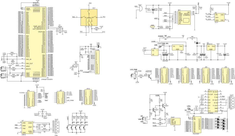
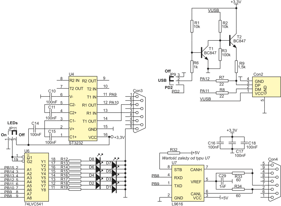
Schematic of ZL27ARM is show on following pictures.
Power supply
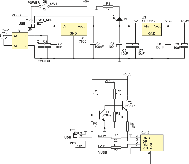
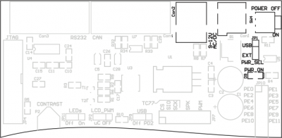
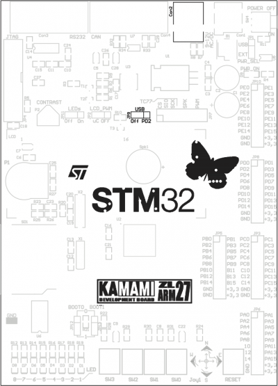
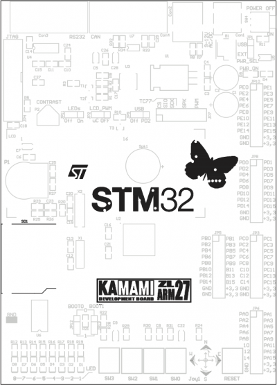
ZL27ARM can be powered from USB (Con2 connector, PWR_SEL jumper in USB position) or from external supply unit (9...12V, Con1 connector, PWR_SEL jumper in EXT position). SW4 is power switch and D9 is power indicator. Board is equipped with +5V and +3,3V voltage regulators. Both voltages are available on pin headers.
Keyboard
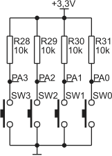
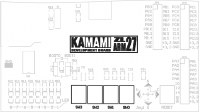
ZL27ARM is equipped with 4-button keyboard (SW0-SW3). All buttons have pull-up resistors. Buttons are connected to PA0-PA3 microcontroller lines. Notice! Microcontroller lines PA0-PA3 are common for keyboard and Joy1 joystick.
Joystick
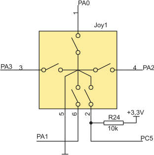
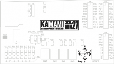
ZL27ARM is equipped with 5-position joystick. All switches have pull-up resistors. Joystick lines are connected to PA0-PA3 and PC5 microcontroller lines. Notice! Microcontroller lines PA0-PA3 are common for keyboard and Joy1 joystick.
LEDs
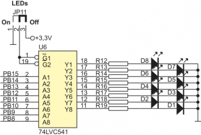
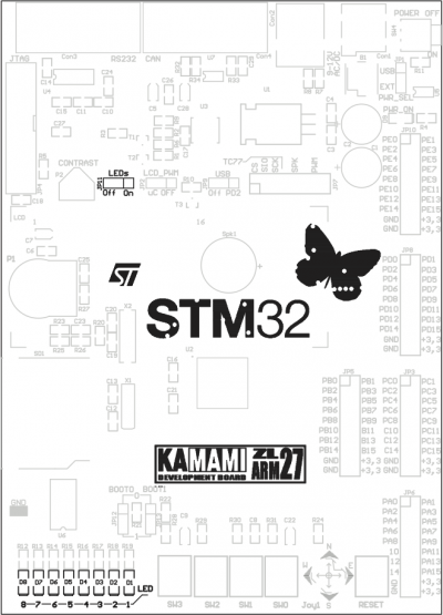
ZL27ARM is equipped with 8 LEDs indicating high level on PB8-PB15 microcontroller lines.
Analog potentiometer
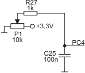
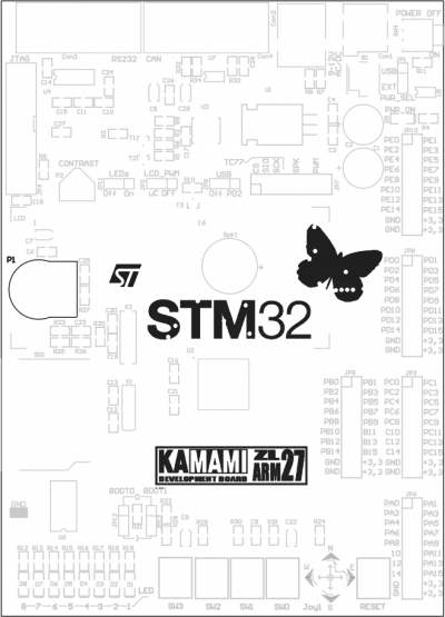
ZL27ARM is equipped with P1 analog potentiometer (voltage range: 0...3.3V). P1 is connected to PC4.
Digital thermometer
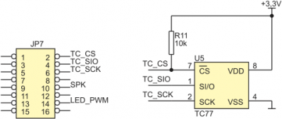
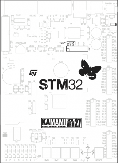
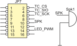
ZL27ARM is equipped with TC77 digital thermometer (by Microchip) with SPI interface. TC77 communication lines (SCK, SIO, CS) are available on JP7 connector.
Piezoelectric speaker
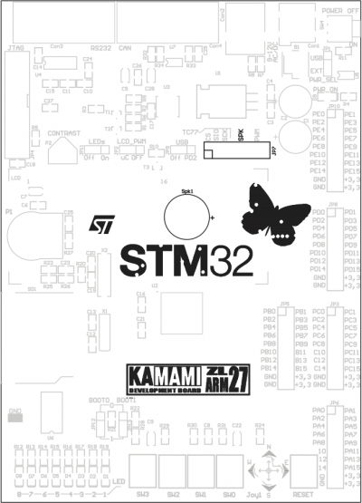
ZL27ARM is equipped with Spk1 piezoelectric speaker. For sound generation you can use microcontroller counters or you can do it programmatically. Speaker is connected to pin SPK on JP7 connector.
Alphanumeric 2x16 LCD connector
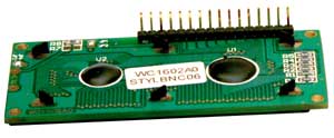
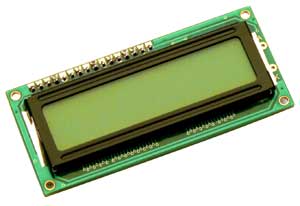
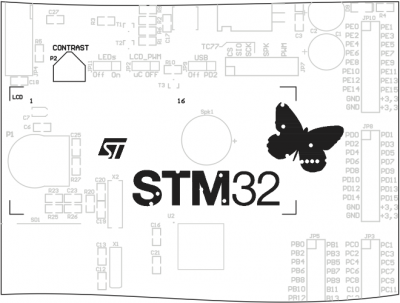
ZL27ARM is equipped with connector for alphanumeric 2x16 LCD connector with HD44780 driver (4-bit mode). Contrast adjustment can be done with P2 potentiometer. LCD control lines are connected to microcontroller as shown in Tab. 1.
| Board is designed to work with alphanumeric 2x16 LCD with pin header (for example LCD1602).
 |
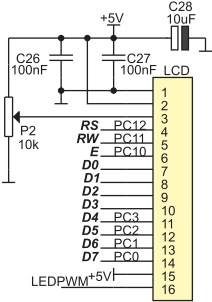
Tab. 1. GPIO lines used to control LCD
| LCD line | GPIO Line |
|---|---|
| D7-D4 | PC0-PC3 |
| E | PC10 |
| RW | PC11 |
| RS | PC12 |
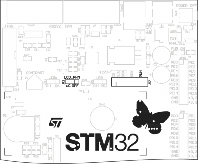
LCD backlight
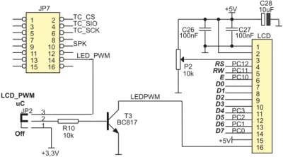
Backlight LEDs in LCD can be powered by NPN transistor (T3). Backlight can be also connected to +3.3V or to PWM by JP2 jumper.
| Position | Description |
|---|---|
| Off | Backlight on |
| uC | Backlight controlled by PWM |
USB interface
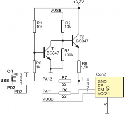
ZL27ARM is equipped with USB-B socket. JP9 jumper sets whether pull-up resistor for D+ is connected to GND (USB not active) or to PD2 microcontroller line.
SD/MMC connector
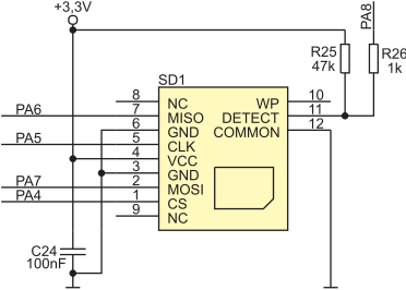
ZL27ARM is equipped with SD/MMC connector (in SPI mode). Socket is connected to SPI1 lines (PA4-PA7 and PA8) of STM32F103VBT6 microcontroller.
BOOT jumpers
ZL27ARM is equipped with BOOT0 and BOOT1 jumpers for boot memory selection (Tab. 2).
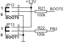
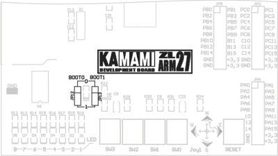
Tab. 2. BOOT jumpers and boot modes
| BOOT0 | BOOT1 | Boot mode |
|---|---|---|
| 0 | X | Flash memory |
| 1 | 0 | System memory |
| 1 | 1 | RAM |
I/O pin headers

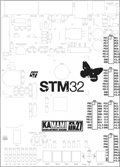
JTAG interface
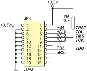
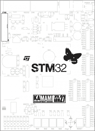
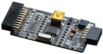
ZL27ARM board is equipped with JP4 connector for programming/debugging using JTAG interface (for example ZL30PRG).
RS232 interface
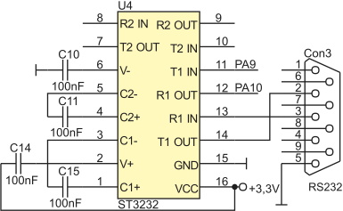
ZL27ARM is equipped with DB9F connector (Con3) and voltage level converter TTL/RS232, that can be used to communicate with PC with RS232 interface. RxD and TxD lines are connected to PA10 and PA9 microcontroller lines (USART1).
CAN interface
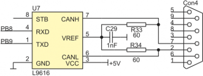
ZL27ARM is equipped with Con4 connector and CAN L9616 converter, which is connected to PB8 and PB9 microcontrolller lines.
