KAPico: Difference between revisions
From Kamamilabs.com - Wiki
No edit summary |
No edit summary |
||
| Line 51: | Line 51: | ||
===== Pin description ===== | ===== Pin description ===== | ||
<center> | <center> | ||
[[File: | [[File: KAPico_wyprowadzenia.png | none | 200px | thumb | center]] | ||
</center> | </center> | ||
<center> | <center> | ||
Latest revision as of 12:06, 9 September 2021

Description
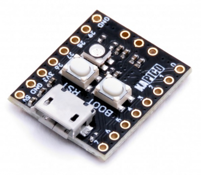
KAPico is a miniature board with RP2040 microcontroller from Raspberry. The board is equipped with 16MB of Flash memory (compared to 2MB of memory on the Raspberry Pi Pico board), connectors with a pitch of 2.54mm allowing for easy attachment of the module to breadboards or universal plates. Thanks to its small dimensions, the product can be used in many development projects.
Basic Features and Parameters
- RP2040 microcontroller designed by Raspberry Pi
- Dual ARM Cortex-M0 + cores clocked up to 133 MHz
- External flash memory: 16 MB
- RAM: 264 KB
- Pads for soldering goldpin connectors
- USB 1.1 works in Host and Device modes
- Support low power mode and idle mode
- Drag & Drop programming possible in USB mass storage mode
- Support for SWD interface for programming and debugging
- 12 GPIO pins
- Extensive communication interfaces:
- 2 x SPI
- 2 x I2C
- 2 x UART
- 4 x 12-bit ADC
- 12 PWM channels
- Built-in real time clock (RTC)
- Accelerator for floating point numbers
- Temperature sensor
- Supply voltage: 3.3 - 5.5 V
- Working temperature: -20 ° C ~ 85 ° C (recommended maximum temperature 70 ° C)
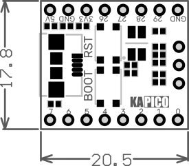
- Dimensions: 17.8mm x 20.5mm
Standard Equipment
| Code | Description |
|---|---|
| KAPico |
|
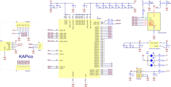
Wiring diagram
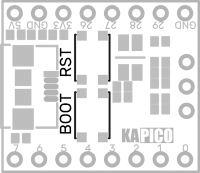
Pin description
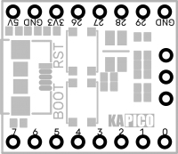
| Pin No. | P1 | Function |
|---|---|---|
| 1 | 7 | GPIO7, SPI0 TX, UART1 RTS, I2C1 SCL, PWM3 B |
| 2 | 6 | GPIO6, SPI0 SCK, UART1 CTS, I2C1 SDA, PWM3 A |
| 3 | 5 | GPIO5, SPI0 CSn, UART1 RX, I2C0 SCL, PWM2 B |
| 4 | 4 | GPIO4, SPI0 RX, UART1 TX, I2C0 SDA, PWM2 A |
| 5 | 3 | GPIO3, SPI0 TX, UART0 RTS, I2C1 SCL, PWM1 B |
| 6 | 2 | GPIO2, SPI0 SCK, UART0 CTS, I2C1 SDA, PWM1 A |
| 7 | 1 | GPIO1, SPI0 CSn, UART0 RX, I2C0 SCL, PWM0 B |
| 8 | 0 | GPIO0, SPI0 RX, UART0 TX, I2C0 SDA, PWM0 A |
| Pin No. | P3 - SWD debug connector | Function |
|---|---|---|
| 9 | SWCLK | Timeline of the debug connector |
| 10 | GND | Mass |
| 11 | SWDIO | Debug connector data line |
| Pin No. | P2 | Function |
|---|---|---|
| 12 | GND | Ground |
| 13 | 29 | GPIO29, ADC3, SPI1 CSn UART0 RX I2C0 SCL PWM6 B |
| 14 | 28 | GPIO28, ADC2, SPI1 RX, UART0 TX, I2C0 SDA, PWM6 A |
| 15 | 27 | GPIO27, ADC1, SPI1 TX, UART1 RTS, I2C1 SCL, PWM5 B |
| 16 | 26 | GPIO26, ADC0, SPI1 SCK, UART1 CTS, I2C1 SDA, PWM5 A |
| 17 | 3V3 | Stabilizer output 3.3V |
| 18 | GND | Ground |
| 19 | 5V | Supply voltage (3.3V - 5.5V) |
Built-in RGB LED
The KAPico module is equipped with a three-color LED diode, which is controlled by the microcontroller terminals that are not connected to the connectors.
| Color | Pin No. |
|---|---|
| Red | GPIO23 |
| Green | GPIO24 |
| Blue | GPIO25 |
BOOT and RST buttons
The KAPico module is equipped with two buttons that facilitate programming of the RP2040 microcontroller. Thanks to the RST button, the user does not have to disconnect and connect the USB cable to reset the microcontroller, while the BOOT button performs the same function as in the Raspberry Pi Pico - it starts the bootloader which allows its programming.
External Dimensions
