ZL41ARM: Difference between revisions
From Kamamilabs.com - Wiki
Anna Kubacka (talk | contribs) No edit summary |
|||
| Line 1: | Line 1: | ||
__jzpdf__ | __jzpdf__ | ||
===== Description ===== | ====== Description ====== | ||
ZL41ARM is a single board computer with a STM32F207/217 microcontroller (Cortex-M3) or STM32F417 (Cortex-M4). The large number of available GPIO lines allows it to be used as a universal microprocessor system with high computational efficiency, thanks i.a. modern design and high frequency CPU clock. | [https://kamami.pl/en/stm32-development-kits/568264-zl41armf207-minicomputer-with-stm32f207-microcontroller-5906623433292.html ZL41ARM] is a single board computer with a STM32F207/217 microcontroller (Cortex-M3) or STM32F417 (Cortex-M4). The large number of available GPIO lines allows it to be used as a universal microprocessor system with high computational efficiency, thanks i.a. modern design and high frequency CPU clock. | ||
<center> | <center> | ||
Latest revision as of 10:28, 2 November 2024

Description
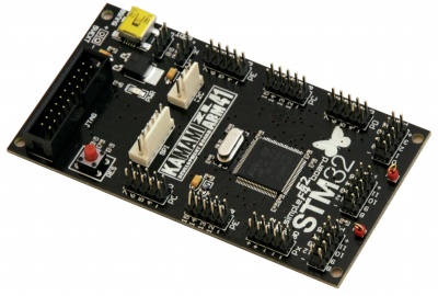
ZL41ARM is a single board computer with a STM32F207/217 microcontroller (Cortex-M3) or STM32F417 (Cortex-M4). The large number of available GPIO lines allows it to be used as a universal microprocessor system with high computational efficiency, thanks i.a. modern design and high frequency CPU clock.

Basic parameters
- STM32F207VE (ARM Cortex-M3, 512 kB Flash, 128 kB RAM), STM32F217VG (ARM Cortex-M3, 1024 kB Flash, 128 kB RAM) or STM32F417VG microcontroller (ARM Cortex-M4, 1024 kB Flash, 192 kB RAM)
- Oscillator 8MHz
- Microcontroller I/O lines available on pin connectors
- JTAG interface connector (20-pin)
- Power supply from USB port (mini USB)
- Jumpers for selecting the boot mode
- Reset button
- I2C and SPI connectors compatible with Kamami standard to connect additional modules
Standard equipment
| Code | Description |
|---|---|
| ZL41ARM_F217 |
Assembled minicomputer with STM32F217VG microcontroller |
| ZL41ARM_F207 |
Assembled minicomputer with STM32F207VE microcontroller |
| ZL41ARM_F417 |
Assembled minicomputer with STM32F417VG microcontroller |
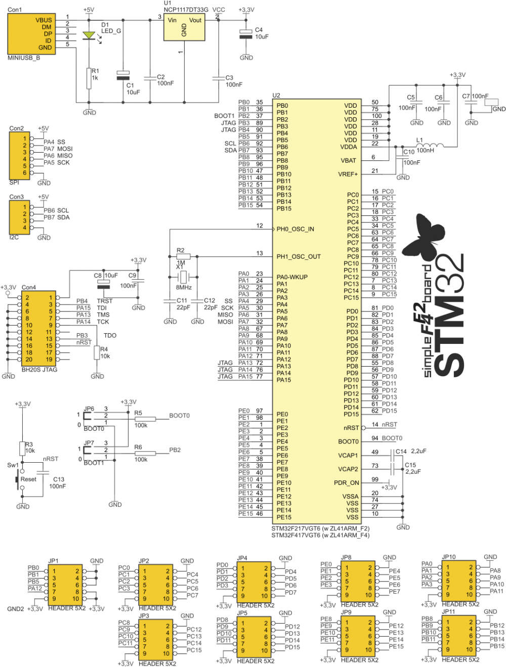
Electrical schematic

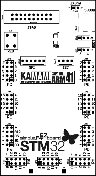
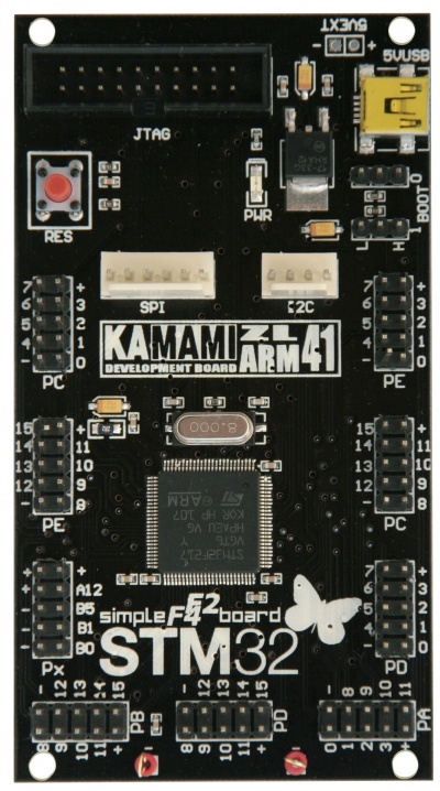
Components placement


BOOT jumpers
ZL41ARM board is equipped with jumpers BOOT0 and BOOT1 (JP6 and JP7) that make possible to select of the memory from which the microcontroller will run (tab. 1).
Tab. 1. BOOT jumper settings and active areas of bootable memory dependent on them
| BOOT0 | BOOT1 | Memory area |
|---|---|---|
| 0 | X | Flash memory |
| 1 | 0 | System memory (bootloader) |
| 1 | 1 | RAM memory |