KAmodBT-HC05: Difference between revisions
From Kamamilabs.com - Wiki
Anna Kubacka (talk | contribs) No edit summary |
m Text replacement - "[[Plik:" to "[[File:" |
||
| Line 4: | Line 4: | ||
<center> | <center> | ||
[[ | [[File:KAmodBT-HC05_modul.png|none|400px|thumb|center]] | ||
</center> | </center> | ||
| Line 37: | Line 37: | ||
===== Electrical schematic ===== | ===== Electrical schematic ===== | ||
<center> | <center> | ||
[[ | [[File:KAmodBT-HC05_schemat.png|none|600px|thumb|center]] | ||
</center> | </center> | ||
===== Output description ===== | ===== Output description ===== | ||
| Line 44: | Line 44: | ||
{| class="wikitable" style="width: 1000px;" | {| class="wikitable" style="width: 1000px;" | ||
|- | |- | ||
! style="text-align: center;" rowspan="10"| [[ | ! style="text-align: center;" rowspan="10"| [[File:KAmodBT-HC05_obrys_PCB.png|center|200px]] | ||
! style="text-align: center;"|JP1 | ! style="text-align: center;"|JP1 | ||
! style="text-align: center;"|Function | ! style="text-align: center;"|Function | ||
| Line 71: | Line 71: | ||
KAmodBT-HC05 module was equipped with LEDs to signalling work mode and connection state with device. By default module settings, green MODE led signals visibility mode (blinking 5 times per second), configuration mode (blinking every 2s) and active mode (double blink every 2s). PAR LED (red) is ON, when communication with device is active. | KAmodBT-HC05 module was equipped with LEDs to signalling work mode and connection state with device. By default module settings, green MODE led signals visibility mode (blinking 5 times per second), configuration mode (blinking every 2s) and active mode (double blink every 2s). PAR LED (red) is ON, when communication with device is active. | ||
<center> | <center> | ||
[[ | [[File:KAmodBT-HC05_diody.png|none|200px|thumb|center]] | ||
</center> | </center> | ||
| Line 77: | Line 77: | ||
KAmodBT-HC05 module was equipped with button for changing work mode - short holding in power supply enabled moment (or by reset) allow to run configuration mode of module (with using AT commands). Parallel with button is connected also KEY line - setting on this line HIGH signal (maximum 3.6V) allow to control work mode from e.g. microcontroller level. This line is pulled down with resistor 10kΩ. | KAmodBT-HC05 module was equipped with button for changing work mode - short holding in power supply enabled moment (or by reset) allow to run configuration mode of module (with using AT commands). Parallel with button is connected also KEY line - setting on this line HIGH signal (maximum 3.6V) allow to control work mode from e.g. microcontroller level. This line is pulled down with resistor 10kΩ. | ||
<center> | <center> | ||
[[ | [[File:KAmodBT-HC05_przycisk.png|none|200px|thumb|center]] | ||
</center> | </center> | ||
Revision as of 17:50, 5 July 2018

Description
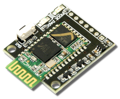
KAmodBT-HC05 is a configurable (by using AT commands) Bluetooth module. Module has integrated LEDs, which signal work mode and connection state with device. Thanks to the small sizes and embedded translator of levels on TxD / RxD lines, module can be used in a lot of development projects.

Basic features and parameters
- HC-05 module with integrated antenna, complies with Bluetooth v2.0 specification
- UART interface with programmable data transfer speed (baudrate)
- Typical receiver sensitivity: -80dBm
- Up to +4dBm RF transmit power
- Embedded voltage regulator
- Possibility of power supply with voltage in range: 2.1V…5.5V
- Embedded voltage level translator on UART lines (TxD, RxD)
- Embedded LED work mode (MODE) and pairing state (PAR)
- Embedded button (running configuration mode)
- KEY and nRST signals on connector
- Sizes: 34.2mm x 27mm x 5mm
Standard equipment
| Code | Description |
|---|---|
| KAmodBT-HC05 |
|
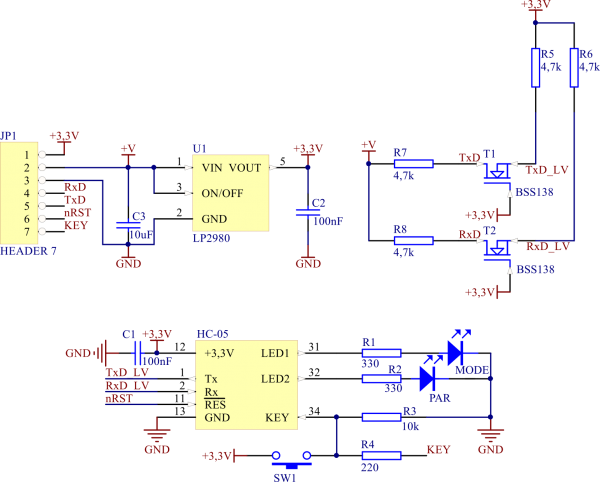
Electrical schematic

Output description
MODE and PAR LEDs
KAmodBT-HC05 module was equipped with LEDs to signalling work mode and connection state with device. By default module settings, green MODE led signals visibility mode (blinking 5 times per second), configuration mode (blinking every 2s) and active mode (double blink every 2s). PAR LED (red) is ON, when communication with device is active.

Work mode button
KAmodBT-HC05 module was equipped with button for changing work mode - short holding in power supply enabled moment (or by reset) allow to run configuration mode of module (with using AT commands). Parallel with button is connected also KEY line - setting on this line HIGH signal (maximum 3.6V) allow to control work mode from e.g. microcontroller level. This line is pulled down with resistor 10kΩ.

External links
Kategoria:Moduły peryferyjne KAmod (Kamami) Kategoria:Zawartość
