ZL3AVR
From Kamamilabs.com - Wiki

Features
- ATmega32 microcontroller in DIP40 package
- Crystal oscillator (16MHz)
- 16-key matrix keyboard (4x4)
- 8LEDs
- Four 7-segment LED displays (multiplexed)
- Alphanumerical LCD display (2x16 characters)
- RS232 interface
- PS/2 connector
- Infrared transmitter and receiver
- AC analog input
- DC analog input
- AC/DC analog output
- ISP connectors (ZL2PRG, ZL11PRG-M)
- JTAG connector
- Connectors with all I/O microcontroller lines
- Power 9VDC/500mA
Package contents :
- assembled board with ATmega32 microcontroller
- 2x16 characters LCD display
ISP programmer connectors
The ZL3AVR board has three connectors for ISP programming:
- Atmel ISP (JP15)
- Kanda ISP (JP20)
- ZL11PRG (JP30)
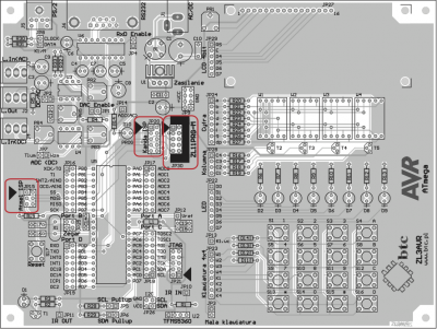
Before connecting ISP programmer make sure that PB port is not connected with any low impedance load circuits.
JTAG connector
The ZL3AVR board has JTAG connector for microcontroller programming and debugging.
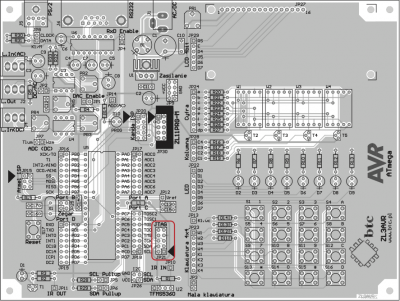
Before connecting JTAG tool make sure that PC port is not connected with any low impedance load circuits. If JTAG is enabled, lines TCK, TDI, TDO and TMS will be unavailable for other purposes.
Keyboard
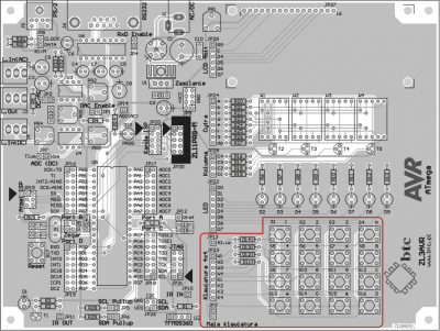
The ZL3AVR board has a 4x4 matrix keypad. When key is pressed column line (K1..K4) is connected to row line (R1..R4). Keypad has signalization line (JP13) which can generate interrupt when key is pressed. Keypad can be also used in normal mode, but only 4 keys will be available. For this mode JP3 connector pin 2 should be connected with pin 1.
LEDs
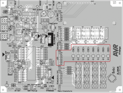
The ZL3AVR board has 8 LEDs for visualization port state. High port state will make LED light. LED anodes are connected to JP22 connector.
LED display
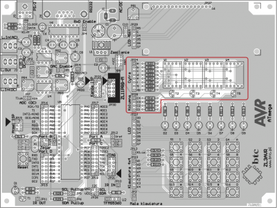
The ZL3AVR board has four 7-segment displays with a common anode. Control signals for display are connected to JP24 and JP28 connectors.
Alphanumerical LCD display
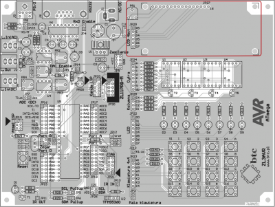
Hitachi HD44780 compatible LCD display can be connected to ZL3AVR board. This display can work only in 4-bit mode without busy flag read.
I2C interface
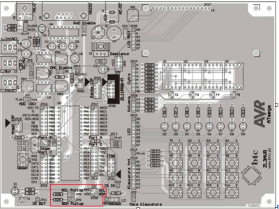
External devices which work with I2C bus can be connected to JP26 connector. Pull-up resistors can be connected to SDA and SCL lines by connecting JP5 and JP6.
RS232 interface
The ZL3AVR board has DB9F connector and MAX232 voltage converter for RS232 interface. Board can be connected to PC using 1:1 cable. Before using RS232 interface JP4 connector must be shorted.
PS/2 interface
The ZL3AVR board has a PS/2 socket for connecting standard PS/2 keyboard or mouse. Before connecting keyboard or mouse make sure that power requirements do not exceed power supply maximum current.
Infrared transmitter and receiver
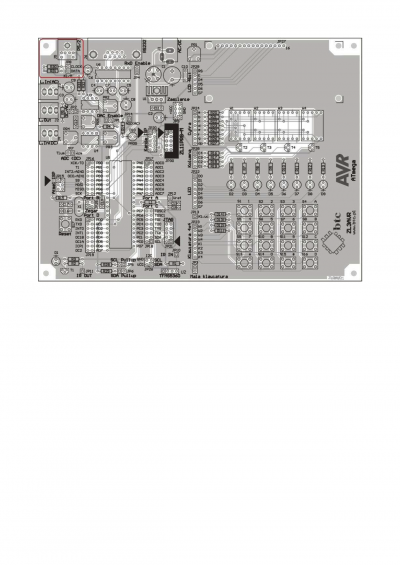
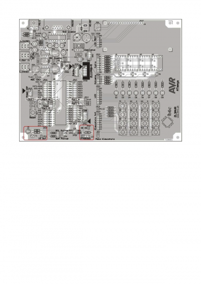
The ZL3AVR board has TFMS5360 (U2) infrared receiver and infrared LED (D1) for transmitting infrared signals.
AC voltage analog input
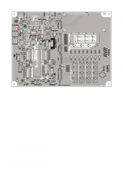
The ZL3AVR board has analog input circuit for AC voltage measurement. This circuit consists of jack connector, polarizing circuit and amplifier with variable amplification. Input voltage amplitude should not exceed 1.2V.
DC voltage analog input
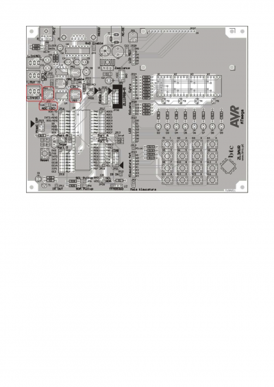
ZL3AVR board has analog input circuit for AC voltage measurement. This circuit consists of jack connector, suppressing circuit (potentiometer) and amplifier. Input voltage should not exceed 5V.
Analog output
ZL3AVR board has low-pass RC filter (7kHz cutoff frequency), resistance divisor, voltage buffer and optionally constant-voltage component separator. This circuit can be used for generating analog voltage using counter 0, that works in PWM mode. If basic frequency on OC0 line is several times higher than 7kHz, output voltage will be linear function of PWM signal width coefficient. Used with counter this circuit is a simple digital to analog converter.