KAmodCOLOR
From Kamamilabs.com - Wiki

Description
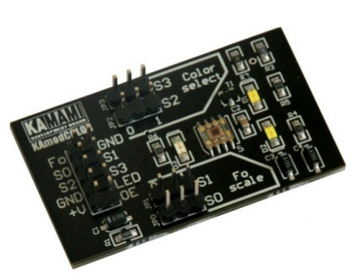
KAmodCOLOR module was built based on the semiconductor color sensor TAOS3200D from TAOS. This system has a matrix with the organization of 8 × 8 photodiodes (16 each with red, green and blue filters and without a filter). It allows measuring the RGB parameter of the light.
Basic features and parameters
- Semiconductor color sensor TAOS3200D from TAOS
- Matrix of 8×8 photodiodes, 16 each with red, green and blue filters and without a filter
- Three LEDs lighting up the tested object
- Digital output with time coding, frequency change depends on lighting intensity
- Power supply 2.7..5.5V
- Tlow power mode (power-down)
Standard equipment
| Code | Description |
|---|---|
| KAmodCOLOR |
|
Electric schematic
View of board
Connectors
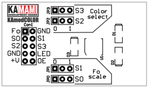
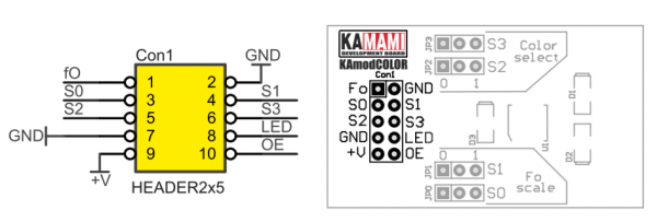
Module is equipped with a connector (Con1), which is used to connect the module to the development board with a 10-pins wire housing with IDC connectors (e.g. CAB_IDC10FF-30 type) or individual wires (e.g. CAB_A type). The description of the functions of each pins are in the table below.
| Pin number | Name | Direction | Function |
|---|---|---|---|
| 1 | Fo | Output | Color sensor output, output with a frequency depending on the light intensity |
| 2 | GND | - | Ground |
| 3 | S0 | Input | Configuration lines of TCS3200D chip. The description of the functions of these lines are in Configuration section |
| 4 | S1 | Input | |
| 5 | S2 | Input | |
| 6 | S3 | Input | |
| 7 | GND | - | Ground |
| 8 | LED | Input | Low state on this line disables the LED backlight (D1, D2 i D3) |
| 9 | +V | - | Power supply 2,7...5,5 V |
| 10 | ~OE | Input | Low state on this line disables this output (Fo line) of TCS3200D chip |
LED backlight
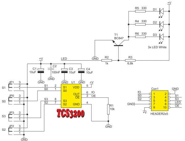
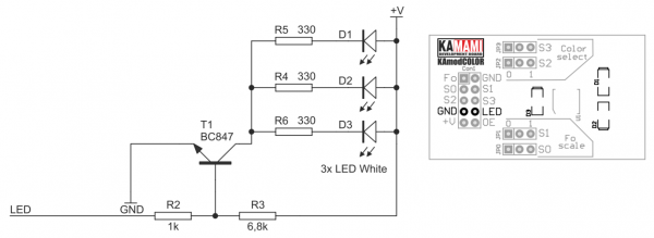
KAmodCOLOR is equipped with white LEDs lighting up the tested object. The LEDs can be disabled by setting a low level on the LED pin of the Con1 connector (for example, by setting the jumpers on pins 7 and 8 of the Con1 connector).
Module configuration
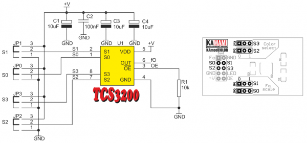
The configuration of TCS3200D chip operation mode can be done by setting logic state 1 or 0 on the Con1 connector on lines S0, S1, S2 and S3. The states of these lines can also be set using jumpers JP0...JP3 (for lines S0...S3). The S0 and S1 lines control the frequency scaling of the output signal and switch the TCS3200D chip into Power-down mode, lines S2 and S3 allow to select the active photodiode section. A description of the functions of these lines are shown in the tables below.
| S0 | S1 | Function |
|---|---|---|
| 0 | 0 | Switching the chip into Power-down mode |
| 0 | 1 | Frequency of the output signal is scaled to 2% |
| 1 | 0 | Frequency of the output signal is scaled to 20% |
| 1 | 1 | Standard frequency of the output signal |
| S2 | S3 | Selected photodiodes |
|---|---|---|
| 0 | 0 | Photodiode with red filter |
| 0 | 1 | Photodiode with blue filter |
| 1 | 0 | Photodiode without filter |
| 1 | 1 | Photodiode with green filter |
