KAmodRPi CAN RS485 HAT
From Kamamilabs.com - Wiki

Description
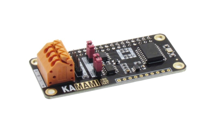
KAmodRPi RS485 CAN HAT is an extension for the Raspberry Pi computer extending its interfaces with RS485 and CAN. The board is equipped with MCP2515 and MCP2551 systems to support the CAN bus, while the conversion of the signal to the levels corresponding to the RS485 bus is the ST3485 system. It allows communication of Raspberry computers with buses used, for example, in automation and vehicles.
Basic Features and Parameters
- Connector compatible with the 40-pin Raspberry standard
- CAN interface
- CAN MCP2515 controller controlled by SPI
- MCP2551 transceiver
- RS485 interface
- ST3485 transceiver (MAX485 compatible)
- Half-duplex transmission
- Automatic detection of transmission direction (direction control possible after two resistors are soldered)
- Signals on the goldpin connectors and terminal strips
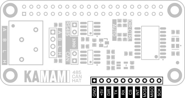
- Additional 2,54mm connector, allowing for work with computers like Arduino
- Built-in jumpers for connecting 120 Ohm terminating resistors
- Dimensions: 65mm x 30mm x 20mm
Standard Equipment
| Code | Description |
|---|---|
| KAmodRPi RS485 CAN HAT |
|
| 4 x Spacer sleeve 8 x Mounting screw |
|
Raspberry Pi Configuration
To use this hat, you need to properly configure the Raspberry Pi (e.g. by the sudo raspi-config command):
- In order to use the RS485 bus, UART must be turned on with the indication that the system shell should be turned off
- To use the CAN bus, you must enable SPI and add the following line in the config.txt file:
| dtoverlay=mcp2515-can0,oscillator=8000000,interrupt=25,spimaxfrequency=1000000 |
|---|
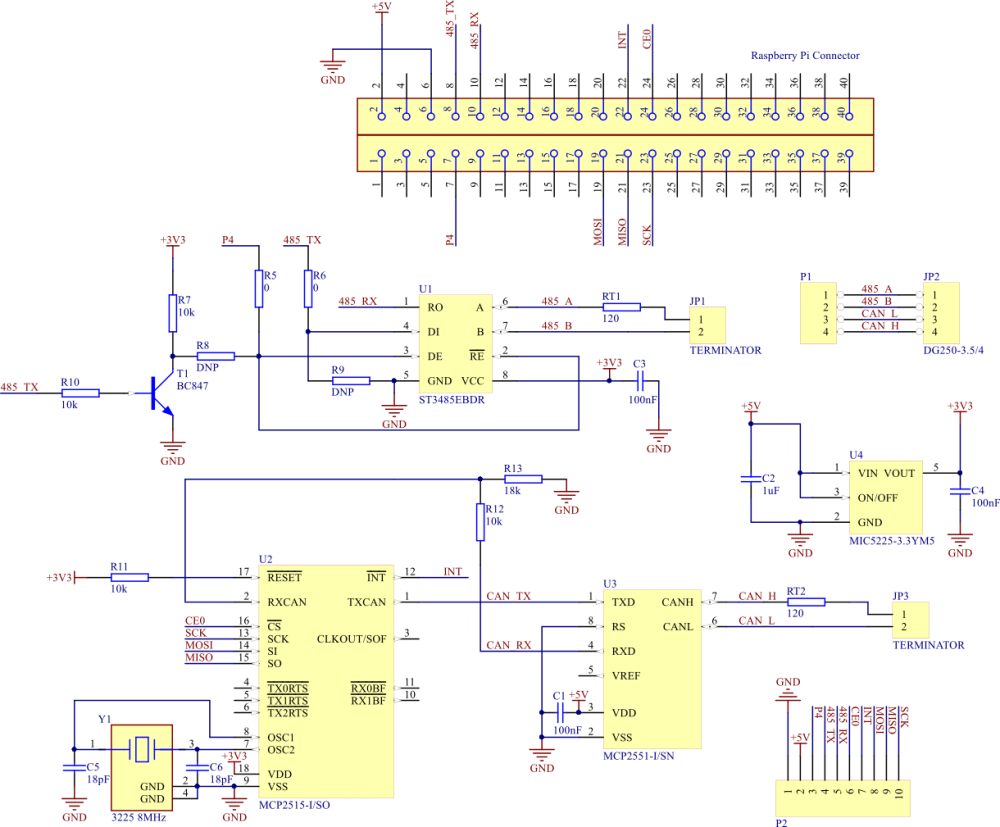
Electronic Schematics
Pin description - bus connectors
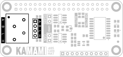 |
JP1 | Function |
|---|---|---|
| 4 (A) | RS485 - inverted signal | |
| 3 (B) | RS485 - non-inverted signal | |
| 2 (L) | CAN Low | |
| 1 (H) | CAN High |
Selecting the operating mode
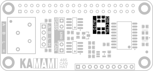
The KAmodRPi RS485 CAN HAT module is equipped with a system that automatically detects the transmission direction. This system, however, is not active; the transmission direction is selected by the GPIO 4 pin state of the Raspberry Pi. In order to save this output, it is possible to switch on the above-mentioned system:
- The jumpers soldered in the DIR CTRL fields (default configuration) mean manual selection of the transmission direction
- Jumpers soldered in AUTO fields mean automatic detection of the transmission direction
Terminating resistors
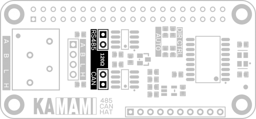
The module is equipped with terminating resistors for both CAN and RS485 buses. These resistors can be disconnected using the following jumpers:
Additional connector
The module has been equipped with an additional connector that allows it to be connected to computers other than those equipped with a 40-pin connector of the Raspberry standard. The pins of the connector are described on the bottom side of the board.
External Dimensions
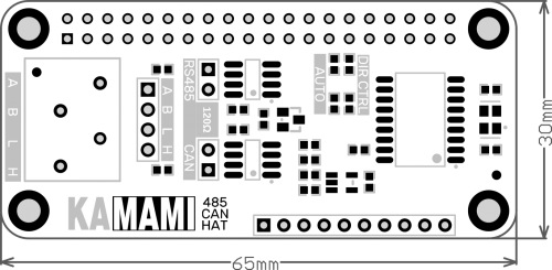
The board has been designed so that the dimensions and mounting holes correspond to the Raspberry Pi Zero board:
