KAmodRPI5 REL POW
From Kamamilabs.com - Wiki

Description
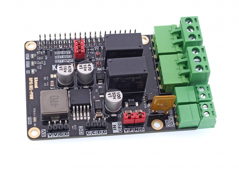
The multifunctional power supply and executive module for Raspberry Pi 5 allows you to power your Raspberry Pi 5 computer from a power source with a voltage of 8 to 32 V. The module also contains two relays with changeover contacts, which allow you to control receivers with a current of up to 3 A. In addition, the board has a digital input circuit with galvanic separation based on an optocoupler. All these functions have been implemented in one compact module, which can be easily connected to the Raspberry Pi 5 and some similar SBCs.

Basic parameters
- Provides power supply with a voltage of 5.1 V with a continuous current of up to 3 A and a short-term current of up to 5 A
- Adapted to input voltage in the range of 8...32 V
- Voltage regulator based on the XL4015 circuit (step-down, 5 A, 180 kHz, 96%)
- Overvoltage, overload and thermal protection
- Two relay outputs with changeover contacts (NC/ON)
- Maximum relay load: 3 A/250 VAC or 3 A/30 VDC
- Digital input with galvanic separation based on an optocoupler
- Digital input parameters: voltage 3.5…32 V (current: 0.5...5 mA)
- Easy installation on Raspberry Pi 5, also with RPi Active Cooler
- Module dimensions 81x56 mm, height approx. 17 mm (and connector under the board approx. 14 mm high)
Standard equipment
| Code | Description |
|---|---|
| KAmod RPI5 REL+POW Mounting kit |
Assembled and launched module A set of screws and spacers for attaching the overlay to the Raspberry board |
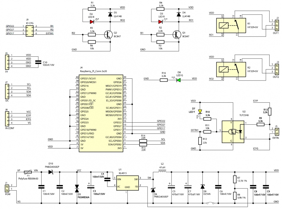
Electrical diagram

Power connector
| Connector | Function |
|---|---|
| POW
Phoenix MC 3.81 mm |
|
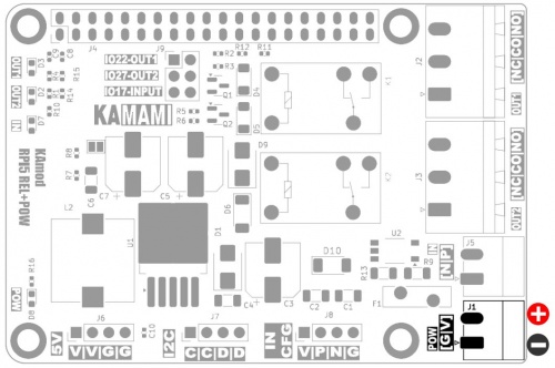
The POW power connector (J1) allows you to connect a direct current (DC) voltage from the range of 8...32 V, from which a voltage of 5.1 V is generated to power the Raspberry Pi. When connecting voltage to the POW connector, pay attention to its correct polarity.
The marking on the board - [G|V] indicates the correct polarity of the power supply:
- G - pin no. 1 is ground, negative power supply pole (GND),
- V - pin no. 2 is the input of the positive power supply pole.
Do not connect a voltage above 34 V. The module contains overvoltage protection, which will disconnect the power supply at a voltage above 34 V.
The connected power source should have adequate power. In order for the module to operate with all parameters (5.1 V/ 5 A), the power of the power supply should not be less than 30 W. Connecting a lower power supply will result in a lower value of the maximum current at the 5 V output.

Relay outputs
| Connector | Function |
|---|---|
| OUT1, OUT2
Phoenix MSTB 5.08 mm |
|
The module contains two HF32F type relays, which allow switching of DC or AC voltage circuits with the following parameters:
- DC – maximum 3 A and 30 V,
- AC – maximum 3 A and 250 V.
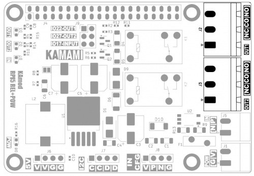
The relays contain changeover contacts, connected to OUT1 (J2) and OUT2 (J3) connectors, in accordance with the [NC|CO|NO] markings on the PCB:
- NO – normally open contact with common contact (Normally Open),
- NC – normally closed contact with common contact (Normally Close),
- CO – common contact (Common).

Input with opto-isolation
| Connector | Function |
|---|---|
| IN
Phoenix MC 3.81 mm |
|
The IN connector (J5) is connected to a TLP2348 digital optocoupler diode. The optocoupler provides galvanic isolation of the IN input, and the built-in Schmitt trigger eliminates many signal interferences. The active state at the optocoupler output is the logical state "0" (L). The maximum frequency of the input signal is approx. 1 MHz.
The signal at the IN input must be a DC voltage in the range of 3.5...32