KAmod IMX477
From Kamamilabs.com - Wiki

Description
KAmod IMX477 - 12.3 MPx Camera Module for Raspberry Pi
The module is equipped with an IMX477 image sensor featuring 12.3 MPx resolution and an M12 mount lens with a 160° field of view. It allows recording video in 1080p30, 720p60, or 640x480p60/90 resolutions. The MIPI CSI-2 lane interface is compatible with Raspberry Pi computers and brought out to a 15-pin FPC/FFC connector. The board features compact dimensions of 26 x 25 mm, making it ideal as a sensor in drones, robotics, or face recognition applications.

Basic Specifications
- Image Sensor Module
- Type: IMX477
- Resolution: 4056 x 3040, 12.3 MP
- Sensor size: 7.9 mm diagonal
- Pixel size: 1.55 μm x 1.55 μm
- Interface: MIPI CSI-2 lane, 15-pin connector, 1 mm pitch
- Default lens mount: M12x0.5 thread
- Video format: 1080p30, 720p60, and 640 × 480p60/90
- Power supply: 3.3 V
- Dimensions: 26 x 25 mm, height with lens approx. 27 mm
- Lens
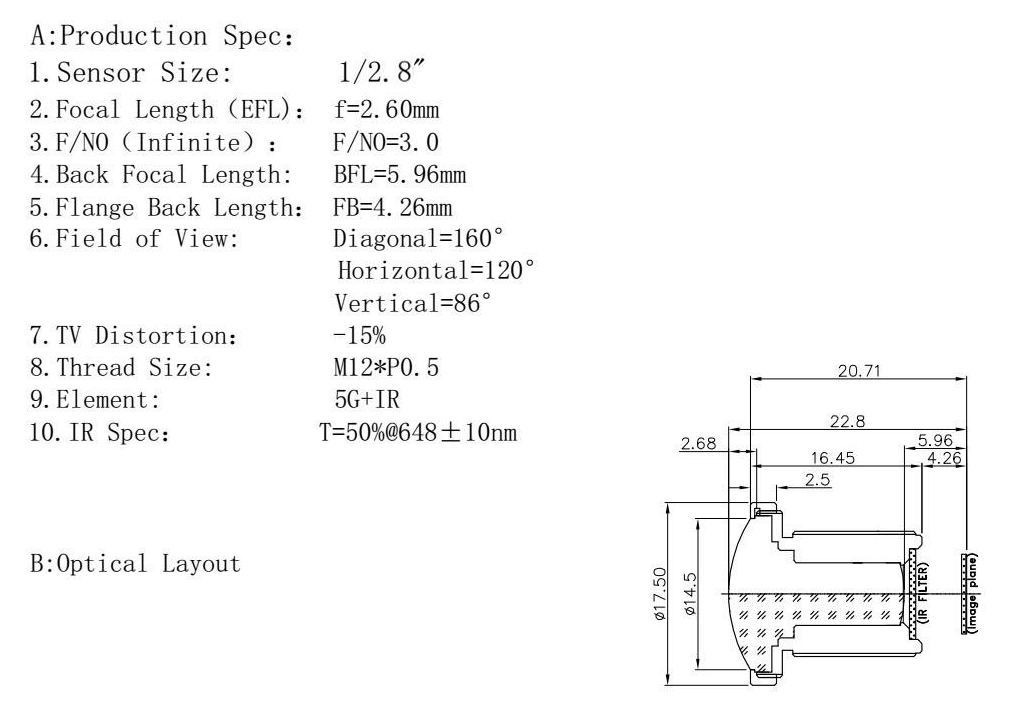
- Focal length (BFL): 5.96
- Optical format: 1/2.8″
- Aperture (F): 3.0
- Field of view (FOV): 160°(D) 120°(H) 86°(V)
- IR sensitivity: built-in IR filter
- Lens standard: M12 (S-mount)
Standard Equipment
| Component | Description |
|---|---|
| KAmod IMX477 |
|
| FPC 15-pin/1mm to 22-pin/0.5mm |
|
| FFC 15-pin/1mm to 15-pin/1mm |
|

Signal Connector
KAmod IMX477 features a MIPI CSI-2 lane interface with a 15-pin/1mm FPC/FFC cable connector. The pin layout is shown in the image below.

Connecting the Module
SBCs feature two types of camera connectors:
- FPC/FFC 15-pin/1 mm, e.g., RPi3, RPi4, Jetson Nano
- FPC/FFC 22-pin/0.5 mm, e.g., RPi5, RPi Zero 2 W, Jetson Orin
The KAmod IMX477 kit includes ribbon cables matching both standards. When connecting, make sure that the metal contacts of the ribbon cable are facing towards the connector contacts, both on the KAmod IMX477 module and on the computer board.
Proper contact orientation is shown in the illustrations.
Connecting the ribbon cable to the KAmod IMX477 module

Connecting the ribbon cable to Raspberry Pi 5

Connecting the ribbon cable to Raspberry Pi 4

Connecting the ribbon cable to Nvidia Jetson Orin Nano

Setting up the Module in Raspberry Pi OS
Connect the KAmod IMX477 camera module to the CAM/DISP0 or CAM/DISP1 connector following the previous instructions.
The new Raspberry Pi OS (Bookworm/Trixie) has built-in support for the IMX477 sensor, so no additional drivers are required. After booting the Raspberry Pi 5 system, you only need to edit the config.txt file. First, run the command:
sudo nano /boot/firmware/config.txt
Now locate the line in the file: camera_auto_detect=1
and change its value to 0: camera_auto_detect=0
Next, add the following to the end of the file under the [all] section:
dtoverlay=imx477,cam0
or
dtoverlay=imx477,cam1
depending on which connector the camera module is attached to. If you connected two camera modules, add both lines.
Finally, save the file using CTRL + O (confirm with Enter) and exit the editor using CTRL + X (confirm with Enter). After rebooting with the sudo reboot command, the single-board computer is ready to use.
You can launch the camera preview using the command:
rpicam-hello -t 0 –camera 0
or
rpicam-hello -t 0 –camera 1
depending on which connector the module is attached to. Press CTRL + C to stop the process.
More information about the rpicam module can be found here:
Raspberry Pi Camera software
Setting up the KAmod IMX477 Camera Module on NVIDIA Jetson Platform
Tested Jetson Orin Nano configuration:
- NVIDIA Jetson Orin Nano Developer Kit Super
- Jetson Linux R39.2.1
- Linux kernel 6.8.12-1021-tegra
- KAmod IMX477 Camera
- Ribbon cable
Support for the original Jetson Nano
The camera is supported via Waveshare IMX477-160 drivers dedicated to the original NVIDIA Jetson Nano board. For JetPack 4.6 and newer versions intended for the original Jetson Nano, camera configuration is performed using the Jetson-IO tool:
sudo /opt/nvidia/jetson-io/jetson-io.py
The menu path in the application is as follows:
Configure Jetson Nano CSI Connector
→ Configure for compatible hardware
→ Camera IMX477 Dual
To test a stream in 1920×1080 resolution at 20 FPS, Waveshare provides the following GStreamer pipeline:
DISPLAY=:0.0 gst-launch-1.0 \
  nvarguscamerasrc sensor-id=0 ! \
  'video/x-raw(memory:NVMM),width=1920,height=1080,format=NV12,framerate=20/1' ! \
  nvoverlaysink -e
Full manufacturer documentation is available on the Waveshare IMX477-160 12.3MP Camera wiki.
The instructions above apply to the original Jetson Nano and (according to Waveshare) Jetson Xavier NX. JetPack 4.6 does not support the Jetson Orin Nano platform and cannot be installed on it.
Native IMX477 Support on Jetson Orin Nano
Before using the camera on the Jetson Orin Nano platform, initial configuration must be performed using the NVIDIA Jetson-IO tool:
sudo /opt/nvidia/jetson-io/jetson-io.py
On the Jetson Orin Nano Developer Kit board, select in sequence:
Configure Jetson 22pin CSI Connector
→ Configure for compatible hardware
→ Camera IMX477 Dual
→ Save pin changes
→ Save and reboot to reconfigure pins
The exact connector name in the menu may vary slightly depending on the Jetson Linux release.
Note:
The camera must be connected while the Jetson board is powered off. Do not connect or disconnect the MIPI CSI camera while the board is connected to power!
Selecting the Camera IMX477 Dual option enables IMX477 sensor definitions for camera connectors. This configuration does not require physically connecting two cameras.
After saving the configuration via Jetson-IO, reboot the system:
sudo reboot
If the Jetson-IO tool reports an error, indicates a missing matching DTB file, or generates a configuration that prevents booting, refer to the troubleshooting section for Jetson Orin Nano Super.
Possible Jetson-IO Issues on Jetson Orin Nano Super
On certain Jetson Orin Nano Super installations, running the command:
sudo /opt/nvidia/jetson-io/jetson-io.py
may fail with an error. One known error message is:
RuntimeError: No DTB found for NVIDIA Jetson Orin Nano Engineering Reference Developer Kit Super!
This issue occurs when the board profile, UEFI/QSPI firmware, installed Jetson Linux release, and DTB files are not compatible with each other. This behavior has been observed particularly with JetPack 6.2 and Jetson Linux R36.4.3 versions.
A discussion on the NVIDIA forum regarding this issue can be found at:
Recommended Recovery Procedure:
- Flash matching QSPI/UEFI firmware and OS image originating from the same Jetson Linux release.
- Do not combine an OS image on an SD card or NVMe drive from one BSP version with QSPI firmware from a different version.
- Using a newer Jetson Linux release where the Jetson-IO tool properly supports the Super profile is recommended.
- Creating a backup before modifying camera configuration is advised:
/boot/extlinux/extlinux.conf
/boot/dtb/
If Jetson-IO generates an invalid boot configuration and UEFI displays the message:
Attempting Recovery Boot
enter the UEFI menu by pressing the Esc key, then select:
Device Manager
→ NVIDIA Configuration
→ L4T Configuration
→ OS chain A status
→ Normal
If an option for a second partition is available, also set:
OS chain B status → Normal
Then select:
L4T Boot Mode → ExtLinux
Save changes and reboot the system. This is the official recovery procedure described by NVIDIA:
NVIDIA Jetson Linux — Set the system to normal boot from recovery kernel boot
Avoid manually renaming or copying random DTB files as a primary fix. A DTB file not tailored to the specific module, carrier board, and BSP release may prevent the system from booting entirely.
Native IMX477 Support on Jetson Orin Nano (Driver)
The Jetson Linux package for Jetson Orin Nano includes a native driver for the IMX477 sensor:
nv_imx477
Once the proper configuration is enabled, the camera appears as a V4L2 device. On the tested R39.2.1 system, the Argus interface provides the following operational modes:
3840×2160 at 30 FPS
1920×1080 at 60 FPS
The driver initializes the sensor, and the NVCSI/VI modules begin receiving frames. However, during testing on version R39.2.1, an issue was observed when Argus automatically controls sensor and ISP gain.
Auto Gain Issue
With default nvarguscamerasrc settings, initial frame captures may be correct. Once Argus begins automatic adjustments, the image turns green with vertical or horizontal striping patterns.
The problem recurred when Argus automatically increased:
- sensor analog gain,
- ISP digital gain.
If the gainrange parameter is omitted, Argus may use the full range reported by the driver (up to approximately 22.25× in the tested configuration). Higher, automatically selected values led to corrupted frame captures.
The image remains stable after limiting both sensor gain and ISP digital gain.
NVIDIA explains that the Argus auto-exposure mechanism continuously calls camera driver functions. Incorrect values or errors in handling functions such as set_exposure() and set_gain() can corrupt Argus capture, even if basic V4L2 communication with the sensor functions properly.
More details are available in NVIDIA documentation:
NVIDIA Camera Software Development Solution — ISP Configuration
Workaround
A practical solution to this issue is:
- keeping auto exposure enabled,
- setting a fixed sensor analog gain,
- locking ISP digital gain to 1×,
- keeping auto white balance enabled.
Key configuration parameters:
aelock=false
gainrange='4 4'
ispdigitalgainrange='1 1'
awblock=false
wbmode=1
Important: Do not omit the gainrange parameter. If omitted, Argus may reset the gain to excessively high values, resulting in a green or corrupted image.
1920×1080 Mode at 60 FPS
Example of a stable GStreamer pipeline:
gst-launch-1.0 \
  nvarguscamerasrc \
    sensor-id=0 \
    aelock=false \
    exposuretimerange='1000000 16000000' \
    gainrange='4 4' \
    ispdigitalgainrange='1 1' \
    awblock=false \
    wbmode=1 ! \
  'video/x-raw(memory:NVMM),width=1920,height=1080,framerate=60/1' ! \
  queue ! nvvidconv ! \
  'video/x-raw(memory:NVMM),format=RGBA' ! \
  nv3dsink sync=false
Exposure time values are provided in nanoseconds:
1 000 000 ns  = 1 ms
16 000 000 ns = 16 ms
At 60 FPS, frame duration is approximately 16.67 ms. Therefore, the maximum exposure limit is set to 16 ms.
If a gain of 4× (gainrange='4 4') proves unstable or unneeded, start testing with a value of 1×:
gainrange='1 1'
Then test higher constant values sequentially:
gainrange='2 2'
gainrange='4 4'
3840×2160 Mode at 30 FPS
4K mode allows for longer exposure times:
gst-launch-1.0 \
  nvarguscamerasrc \
    sensor-id=0 \
    aelock=false \
    exposuretimerange='1000000 32000000' \
    gainrange='4 4' \
    ispdigitalgainrange='1 1' \
    awblock=false \
    wbmode=1 ! \
  'video/x-raw(memory:NVMM),width=3840,height=2160,framerate=30/1' ! \
  queue ! nvvidconv ! \
  'video/x-raw(memory:NVMM),format=RGBA' ! \
  nv3dsink sync=false
At 30 FPS, frame duration is approximately 33.33 ms. The practical maximum exposure value is roughly 32–33 ms:
exposuretimerange='1000000 32000000'
Conservative configuration for 4K mode using 1× gain:
gst-launch-1.0 \
  nvarguscamerasrc \
    sensor-id=0 \
    aelock=false \
    exposuretimerange='1000000 32000000' \
    gainrange='1 1' \
    ispdigitalgainrange='1 1' \
    awblock=false \
    wbmode=1 ! \
  'video/x-raw(memory:NVMM),width=3840,height=2160,framerate=30/1' ! \
  queue ! nvvidconv ! \
  'video/x-raw(memory:NVMM),format=RGBA' ! \
  nv3dsink sync=false
Selected gain values should be verified for the specific camera module unit, lighting conditions, chosen sensor mode, and Jetson Linux system release.
Module Dimensions
The board dimensions are 26 x 25 mm, and the height including the lens is approx. 27 mm. The board includes mounting holes; their layout is shown in the image below.