MAXimator Expander
From Kamamilabs.com - Wiki

Description
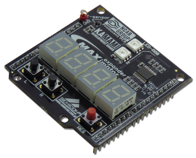
MAXimator Expander is an extension module with an embedded temperature sensor, 7-segment displays, keyboard and multi-colored LEDs. The board is dedicated to work with MAXimator
Basic features and parameters
- STLM20W87F temperature sensor from STMicroelectronics
- Four 7-segment displays, multiplex controlled
- Embedded 74LVC2244A (buffer powered displays)
- Two multi-colored (RGB) LEDs WS2812B type
- Embedded two user buttons and reset button
- Mounting holes 3mm
- Module size: 5 mm x 55mm x 19mm
| Board is not compatible with Arduino! |
Standard equipment
| Code | Description |
|---|---|
| MAXimator Expander |
|
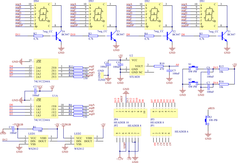
Electrical schematic
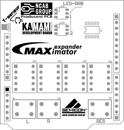
View of board

Temperature sensor
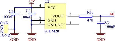
On MAXimator Expander board is placed integrated STLM20 temperature sensor with an analog signal output. The signal output is available on the A0 line. The output voltage of chip represents the measured temperature, according to the transfer function:
where:
T – temperature measured by sensor
Vo – output voltage
Measured temperature has a value:
7-segment displays
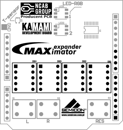
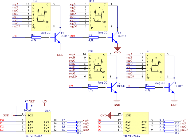
On board are mounted four 7-segment LED displays, multiplex-controlled via 74LVC2244A chip.
| Line | LED segment |
|---|---|
| D0 | segment A |
| D1 | segment B |
| D2 | segment C |
| D3 | segment D |
| D4 | segment E |
| D5 | segment F |
| D6 | segment G |
| D7 | segment DP |
| D8 | cathode DS1 |
| D9 | cathode DS2 |
| D10 | cathode DS3 |
| D11 | cathode DS4 |

Multi-colored LEDs (RGB)
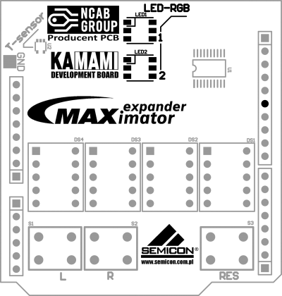
Embedded multi-colored WS2812 diodes allow for displaying colors in more than 16.7 million shades, diode control is in series - with one signal line it is possible to control a series of such diodes. The D12 line supplies the control signal to the LED1 input, its output is connected to the LED2 input.

Buttons
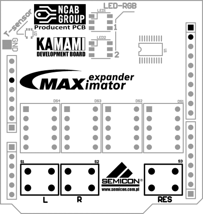
Board has two user buttons (marked "L" and "R") and a system reset button. Signal lines D14 and D15 (to which the "R" and "L" buttons are connected) are pulled up to the supply voltage (+5V). Reset button (RES) is connected to the nRST line, pressed to connect the line to the ground.
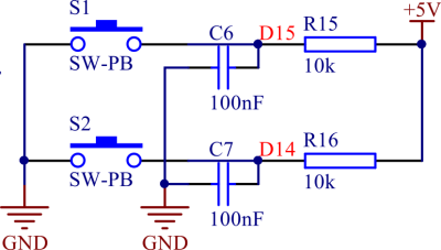

| Key | Line | Default state |
|---|---|---|
| „L” (S1) | D15 | Pull up to power supply (+5 V) |
| „R” (S2) | D14 | Pulled up to power supply (+5 V) |
| RES (S3) | nRST | Disconnected |