KA-Nucleo-Weather
From Kamamilabs.com - Wiki

Description
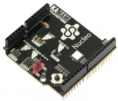
KA-Nucleo-Weather is an functional expander for NUCLEO and Arduino boards with set of environmental sensors: pressure, humidity, temperature and light intensity sensors as well as 5-way joystick and RGB LED.
Basic features and parameters
- Compatibility with NUCLEO and Arduino systems
- Embedded MEMS pressure sensor (LPS331):
- Measurement range 260 to 1260mbar
- Measurement output data rate (ODR) 1 Hz to 25 Hz
- ADC resolution 16 bits
- Interface: SPI/I2C (used I2C)
- Embedded MEMS humidity sensor (HTS221):
- Measurement range 0 to 100% (relative humidity)
- Measurement output data rate (ODR) 1 Hz to 12,5 Hz
- ADC resolution 16 bits
- Interface: SPI/I2C (used I2C)
- Embedded digital temperature sensor (STLM75):
- Measurement range –55°C to +125°C
- ADC conversion time <150ms
- Integrated programmable thermostat
- ADC resolution 9 bits
- Interface: SMbus/I2C
- Embedded digital light intensity sensor ALS (TSL25721):
- Approximates human eye response
- Integrated analog amplifiers with programmable gain
- Two measurement canals
- Integrated programmable comparators
- Measurement dynamic range 45,000,000:1
- Maximum light intensity to 60000 lux
- ADC resolution 16 bits
- Embedded RGB LED
- Embedded 5-way joystick
- Extended pins connector
Standard equipment
| Code | Description |
|---|---|
| KA-Nucleo-Weather |
|
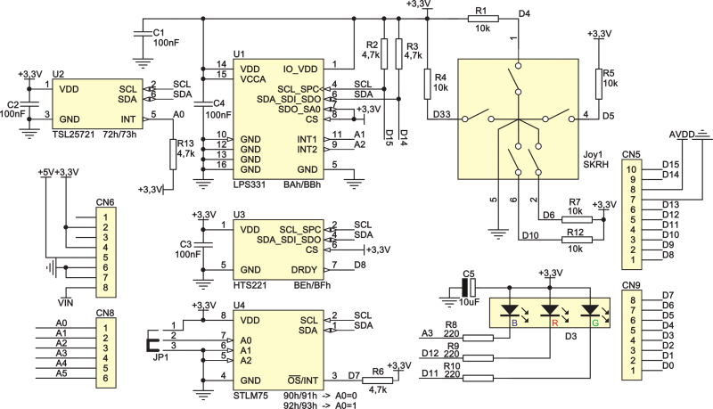
Electrical schematics
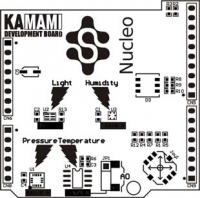
Board view
Temperature sensor
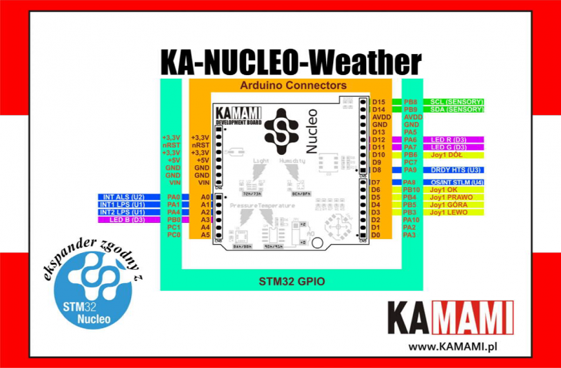
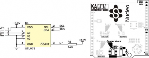
In expander was used semiconductor temperature sensor STLM75 with digital output. Communication interface of temperature sensor is connected to common (for all sensors) I2C bus. Communication lines of I2C interface are pulled up to power supply by 4,7 kΩ resistors. Connection method of temperature sensor to microcontroller is showing on schematic. Output of temperature sensor is connected to line A2, which is input canal of ADC_IN4 (PA4 GPIO pin of STM32).
| Line STLM75 | Line name | GPIO in STM32 | STM32 interface | Comments |
|---|---|---|---|---|
| SCL | D15 | PB8 | I2C1 | Lines was pulled up to power supply lines by 4,7 kΩ resistors |
| SDA | D14 | PA9 | ||
| OS/INT | D7 | PA8 | - |
Jumper JP1 make possible choosing base address of STLM75 chip according to table below:
| Closed pins JP1 | A0 | I2C base address |
|---|---|---|
| 1-2 | 1 | 90h/91h |
| 2-3 | 0 | 92h/93h |
Light intensity sensor (ALS)
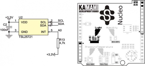
Expander is equipped with digital sensor of light intensity in environment TSL25721. Sensor has I2C interface. Communication bus of this sensor is connected to common (for all sensors) I2C bus. I2C communication lines are pulled up to power supply by 4,7 kΩ resistors. Connection method of TSL25721 sensor to microcontroller is showing on schematic.
| Line TSL25721 | Line name | GPIO in STM32 | STM32 interface | Comments |
|---|---|---|---|---|
| SCL | D15 | PB8 | I2C1 | Lines was pulled up to power supply lines by 4,7 kΩ resistors |
| SDA | D14 | PA9 | ||
| INT | A0 | PA0 | - | - |
TSL25721 sensor is placed in I2C bus under base address 72h/73h.
Humidity sensor
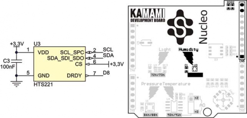
Expander is equipped with digital humidity sensor HTS221 with I2C communication interface. Communication bus of this sensor is connected to common (for all sensors) I2C bus. I2C communication lines are pulled up to power supply by 4,7 kΩ resistors. Connection method of HTS221 sensor to microcontroller is showing on schematic.
| Line HTS221 | Line name | GPIO in STM32 | STM32 interface | Comments |
|---|---|---|---|---|
| SCL | D15 | PB8 | I2C1 | Lines was pulled up to power supply lines by 4,7 kΩ resistors |
| SDA | D14 | PA9 | ||
| DRDY | D8 | PA9 | - | - |
HTS221 sensor is placed in I2C bus under base address BEh/BFh.
Pressure sensor
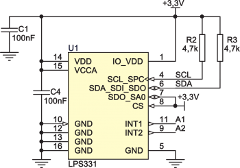
Expander is equipped with digital pressure sensor LPS331 with I2C communication interface. Communication bus of this sensor is connected to common (for all sensors) I2C bus. I2C communication lines are pulled up to power supply by 4,7 kΩ resistors. Interrupt output (INT1 and INT2) of sensor LPS331 can work in push-pull mode and don't need pulling up to power supply. Connection method of LPS331 sensor to microcontroller is showing on schematic.
| Line LPS331 | Line name | GPIO in STM32 | STM32 interface | Comments |
|---|---|---|---|---|
| SCL | D15 | PB8 | I2C1 | Lines was pulled up to power supply lines by 4,7 kΩ resistors |
| SDA | D14 | PA9 | ||
| INT1 | A1 | PA1 | - | Outputs should be configured as push-pull |
| INT2 | A2 | PA4 | - |
LPS331 sensor is placed in I2C bus under base address BAh/BBh.
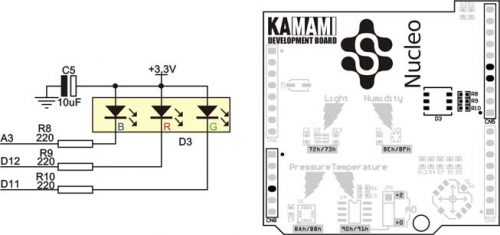
LED-RGB
On-board LED-RGB are controlled direct with GPIO pins of microcontroller (according to table below). Diodes are on, if state of control line has logical state „0”.
| LED | Line name | GPIO in STM32 | Comments |
|---|---|---|---|
| Red | D12 | PA6 | LEDs are on, if state on GPIO pins is „0” |
| Green | D11 | PA7 | |
| Blue | A3 | PB0 |
Joystick
Embedded 5-way tact switch is connected direct to GPIO pins of microcontroller (according to table below). Each of pins are pulled up to power supply by using 10 kΩ resistor.
| Joystick direction | Line name | GPIO in STM32 | Comments |
|---|---|---|---|
| Up | D4 | PB5 | Lines pulled up to power supply by 10 kΩ resistor. |
| Down | D10 | PB6 | |
| Left | D3 | PB3 | |
| Right | D5 | PB4 | |
| OK | D6 | PB10 |
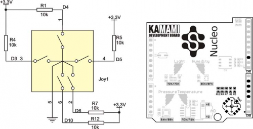
Signal connections map of GPIO pins
