ZL42ARM
From Kamamilabs.com - Wiki

Description
ZL42ARM is a universal 32-bits minicomputer with microcontroller STM32F103 (Cortex-M3) with integrated prototype area. Equipment of the board is maximum simple - all GPIO lines are available on goldpin connectors (2.54mm). On board are also used convenient SPI and I2C connectors.
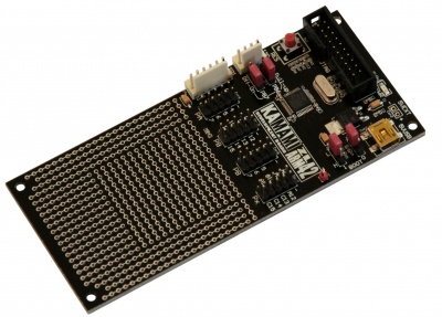
Basic parameters
- Microcontroller STM32F103C6 (ARM Cortex-M3 @72MHz, 32 kB Flash, 10 kB RAM, LQFP48 package)
- Oscillator 8MHz
- 30 microcontroller I/O line on goldpin connectors
- JTAG interface connector (20-pins)
- Power supply via USB (mini USB)
- LED for power supply signalling
- Jumper for boot way select
- Reset button
- I2C and SPI connectors compatible with Kamami standard for additional KAmod modules
- Universal area with 520 holes
Standard equipment
| Code | Description |
|---|---|
| ZL42ARM |
|
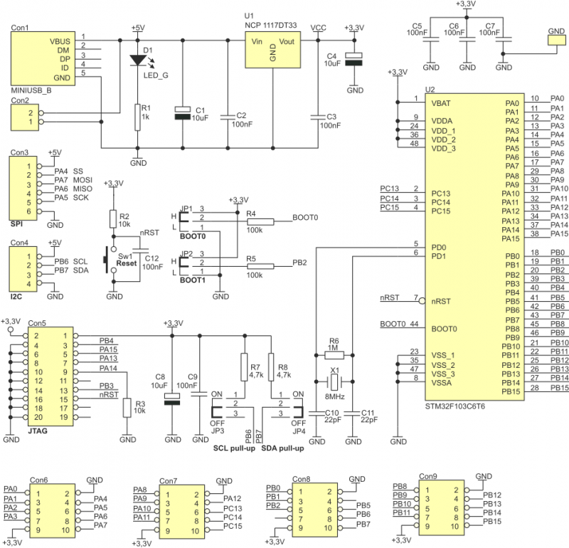
Electrical schematic
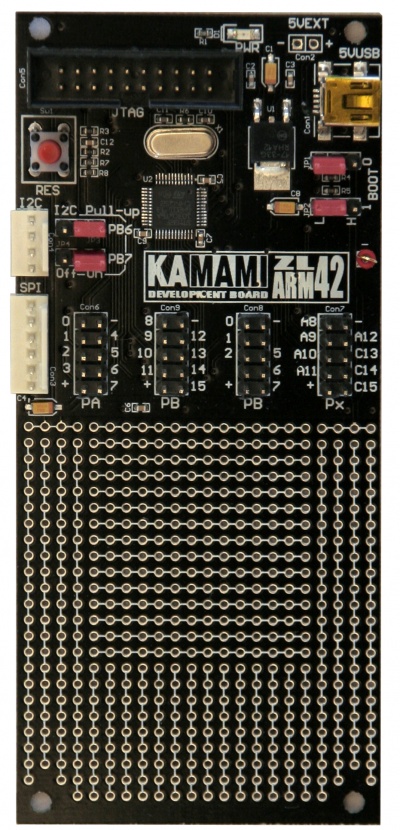
Components placement
Power supply
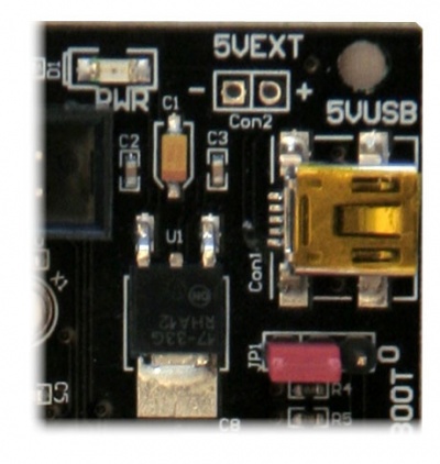
Board should be supply with 5V power supply source via miniUSB or via optional mounting goldpin connector marked as 5VEXT.
Connect of power supply to the board via one of listed connectors turns on PWR LED on the board.
BOOT Jumpers
ZL42ARM board is equipped with BOOT0 and BOOT1 jumpers (JP1 and JP2) that make possible selection of memory for boot process of microcontroller (Table 1).
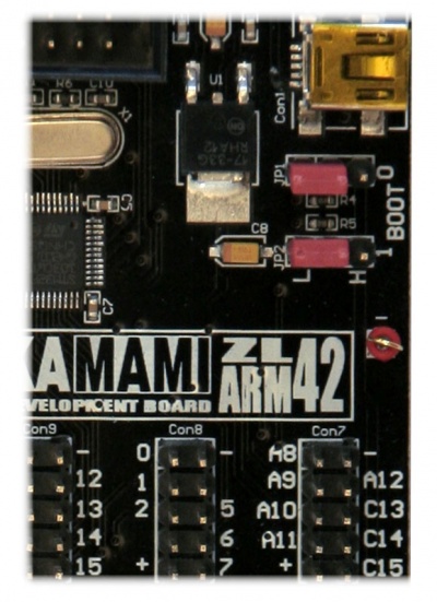
Tab. 1. BOOT jumper settings and corresponding active start memory areas
| BOOT 0 | BOOT 1 | Memory area |
|---|---|---|
| 0 (L) | X | Flash memory |
| 1 (H) | 0 (L) | System memory (bootloader) |
| 1 (H) | 1 (H) | RAM memory |
Pull-up jumper of I2C lines
ZL42ARM board is equipped with JP3 and JP4 that allow to connect to SDA and SCL lines of I2C bus via pull-up resistors to power supply voltage +3.3V (Table 2).
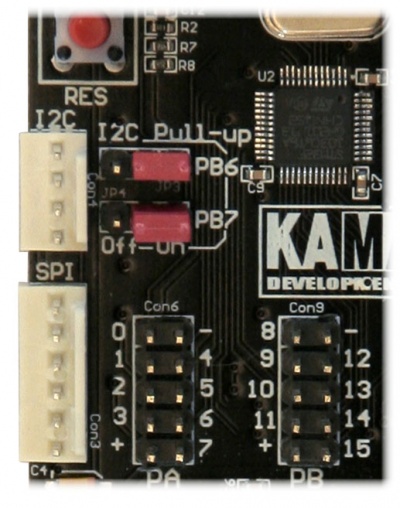
Tab. 2. Functions of pull-up resistor jumpers
| JP3 | JP4 | Description |
|---|---|---|
| 1-2 | X | Enable pull-up on SCL (PB6) |
| 2-3 | X | Disable pull-up on SCL (PB6) |
| X | 1-2 | Enable pull-up on SCL (PB7) |
| X | 2-3 | Disable pull-up on SCL (PB7) |