KAmodRPi UART RS485 ISO
From Kamamilabs.com - Wiki

Description
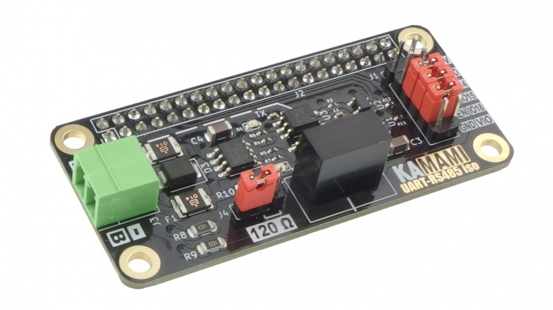
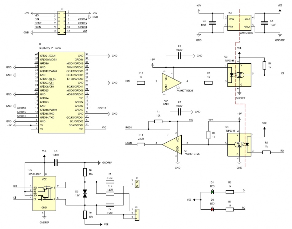
KAmodRPi UART RS485 ISO is an RS485 bus transceiver controlled from the UART interface, compatible with the Raspberry Pi SBC family. On the RS485 bus side, the MAX13487 system is used, which has an automatic transmission direction control function. This solution requires only 2 signals - RXD and TXD for correct, bidirectional communication using the standard UART interface. The control signals are connected via circuits providing galvanic separation. Additionally, the module is equipped with overvoltage protection on the RS485 bus lines and allows the connection of a 120 Ω resistance acting as an RS485 bus terminator.
Basic features and parameters
- RS485 bus transceiver module controlled from the UART interface
- MAX13487 RS485 bus transceiver
- Automatic switching between transmitting/receiving data
- Only 2 RXD and TXD signals needed for correct, bidirectional communication (does not require the TX ENABLE signal)
- Half-duplex communication
- Transmission speed - max 500 kbps
- Number of modules connected to the bus - max 128
- Independent power supply for RXD and TXD line circuits enabling cooperation with systems operating with a voltage in the range of 2.0-5.5 V (does not require additional voltage translators)
- Data transmission/receiving signaling - diodes LED
- Connected resistance 120 Ω (bus terminator)
- Possibility of blocking data reception (blocking the RXD signal)
- Galvanic isolation up to 1 kV
- Overvoltage protection on RS485 bus lines
- RS485 bus connector type Phoenix Contact MC 3.81 mm
- 5 V power supply via RPi Zero standard connector or goldpin pins
- Current consumption max 100 mA
- Operating temperature: -40°C ~ 85°C
- Board and connector in Raspberry Pi Zero standard
- Dimensions: 65 mm x 30 mm x 20 mm
Standard equipment
| Code | Description |
|---|---|
| KAmodRPi UART RS485 ISO |
|
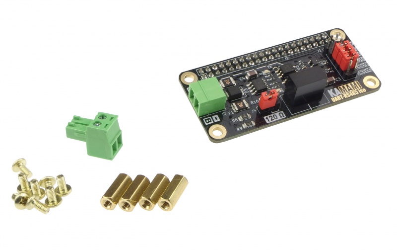
| 4 x Mounting sleeve 8 x Mounting screw |
|
Wiring diagram
Pinout
J1 (goldpin 2x5, 2.54 mm pitch)
| Pin number | Designation | Function |
|---|---|---|
| 1, 2 | +5V | 5 V power input |
| 3, 12 | VIO | Power input defining the voltage level on the UART interface |
| 4, 11 | GND | Power ground input |
| 5 | DIN | Data input - from the UART interface |
| 6 | GPIO14 | Transferred GPIO14 (TXD) signal from RPi connector |
| 7 | DOUT | Data output - to UART interface |
| 8 | GPIO15 | Transferred GPIO15 (RXD) signal from RPi connector |
| 9 | RXEN | Data reception blocking input:
1 – reception active, 0 – reception blocked (internally pulled up to 1) |
| 10 | GPIO18 | GPIO18 signal transferred from RPi connector |
J2 (goldpin 2x20, 2.54 mm pitch)
| Connector type | Function |
|---|---|
| 40-pin connector
standard Raspberry Pi |
|
J3 (Phoenix Contact MC 3.81 mm)
| Pin No. | Designation | Function |
|---|---|---|
| 1 | A, + | RS485 transceiver positive output/input recessive state A>B, dominant state A<B |
| 2 | B, - | RS485 transceiver negative output/input recessive state A>B, dominant state A<B |
J4 (goldpin 1x3, 2.54 mm pitch)
| Connector type | Function |
|---|---|
| Goldpin + jumper |
|
Bus terminator
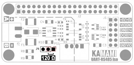
The module allows you to connect a 120 Ω resistor to the RS485 bus line, acting as a so-called bus terminator. This solution should only be used when the module is located at one of the ends of the RS485 bus. The function is active when the jumper is located on pins 1-2 J4.
UART data input/output
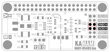
The TX signal coming out of the UART interface should be connected to the DIN J1 pin. The RX signal that will go to the UART interface should be connected to the DO J1 pin.
If the module is connected to a Raspberry Pi SBC, it is enough to put on 2 jumpers connecting the DIN-IO14 and DO-IO15 pins to connect the module to the RPi computer's UART interface - GPIO14 (TXD) and GPIO15 (RXD) pins.
Possibility of blocking data reception (blocking the RXD signal)
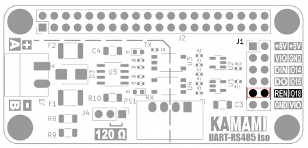
The RX signal that will reach the UART interface from the DO J1 pin can be blocked (e.g. when the application is starting and is not ready to receive data). The data reception blocking input is the REN J1 pin. When it is in the high state "1" - data reception works normally; when it is in the low state "0" - data reception is blocked, the output is in a high impedance state. The REN signal is internally pulled up to "1". If the module is connected to a Raspberry Pi SBC, simply place a jumper on the REN-IO18 pins to connect the REN signal to the GPIO18 pin of the RPi computer.
Powering the module
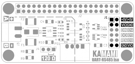
The module can be used without connecting to a Raspberry Pi SBC. In this case, you should connect a 5V power supply (min 100mA) to the +5V and GND pins of the J1 connector. In addition, a power supply with a voltage in the range of 2.0...5.5V (approx. 10 mA) should be supplied to the VIO and GND contacts. The VIO voltage determines the voltage level of the DIN and DO signals that will be connected to the TX and RX lines of the UART interface. The +5V, GND and VIO contacts appear twice on the connector, but they are the same signals (it is enough to connect 5V to one of the +5V contacts).
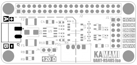
RS485 bus connector
The module is equipped with a Phoenix Contact MC 3.81 mm RS485 bus connector. It provides easy assembly of cables and allows for quick connection/disconnection.
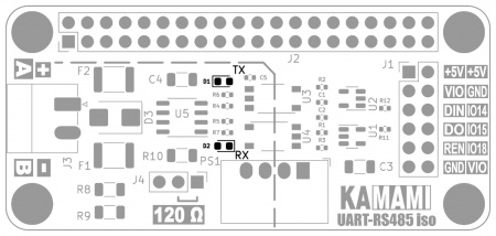
Transmit/receive signaling
The module signals the transmission/reception of data to/from the RS485 bus using miniature LED indicators, marked on the board as TX and RX, respectively.
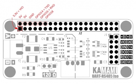
GPIO connector compatible with Raspberry Pi SBCs
The board contains a 40-pin J2 connector compatible with the Raspberry Pi SBC GPIO connector. Signals important for the module's operation are marked in the figure. They are also connected to the appropriate pins on the J1 connector.
Installing the module on the Raspberry Pi computer connector
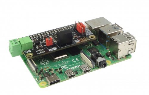
Installing the module on the Raspberry Pi computer connector
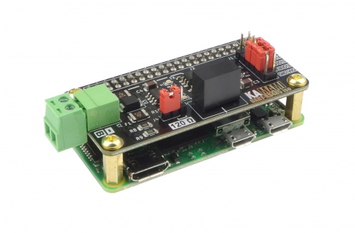
Installing the module on the Raspberry Pi Zero computer connector
| The Raspberry Pi computers shown in the pictures are not included in the set. |
|---|
Dimensions
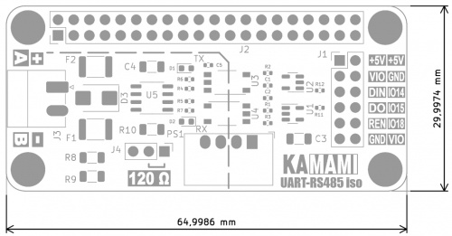
The board has been designed to match the dimensions and mounting holes of the Raspberry Pi Zero board.
