KAmod CAN-TXRX
From Kamamilabs.com - Wiki

Description
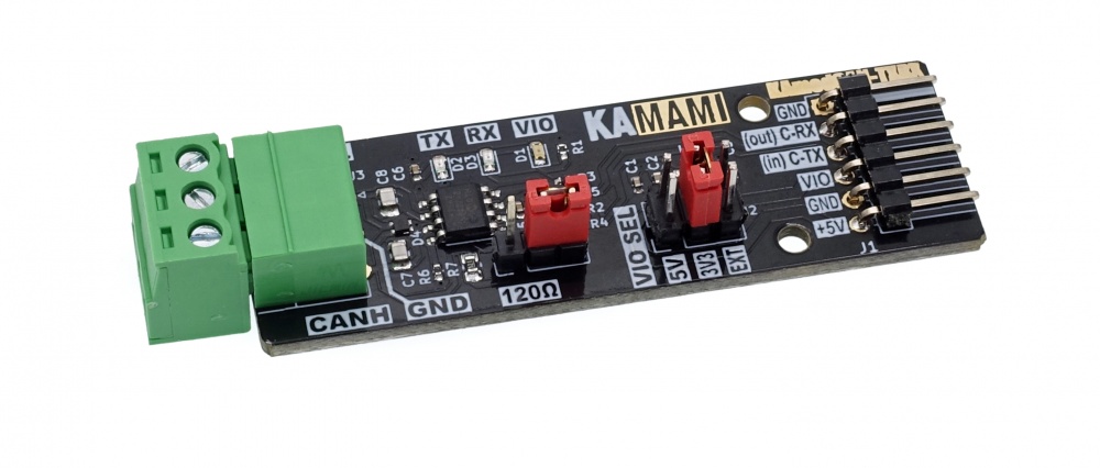
KAmod CAN-TXRX is a CAN bus transceiver with the MCP2542FD system. It allows you to send and read data from the CAN bus operating in the latest CAN 2.0 and CAN FD standards and includes a number of safeguards to protect against damage. The module is not a CAN bus controller - it must receive the appropriate data frames, compliant with the CAN standard, from the control system - e.g. a microcontroller. Communication with the module takes place via a serial interface with C-RX and C-TX signals. The serial interface voltage level can be set in the range of 1.7...5 V. The values of 5 V and 3 V can be easily selected using jumpers on the board, while another, non-standard voltage value should be connected to the VIO pin. The transceiver module is equipped with diodes indicating correct power supply and communication.
Basic parameters
- CAN bus transceiver, compatible with CAN 2.0 and CAN FD
- Based on the MCP2542FD
- Communication via serial interface with RX and TX signals
- The voltage level of the serial interface can be set in the range of 1.7...5 V
- Additional VIO input defining the voltage level of the serial interface
- Communication speed (bit rate): 14.4 kbps...8 Mbps
- Power supply 5 V, 100 mA
- Connectable 120 Ω terminating resistor
- LEDs indicating correct power supply and communication
- CAN bus lines connected via Phoenix MC 3.81 mm connector
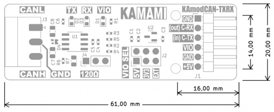
- Board dimensions 61x20 mm, height approx. 12 mm
Standard equipment
| Code | Description |
|---|---|
| KAmod CAN-TXRX | Assembled and started module |
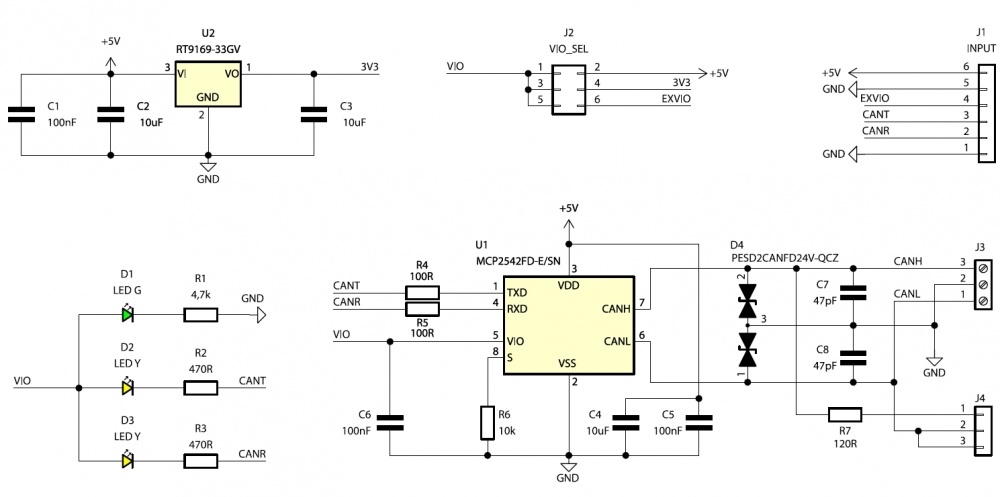
Wiring diagram
Control connector
| Connector | Function |
|---|---|
| J1
1x6 goldpin pins, 2.54 mm |
|
The control connector contains a serial data input and a serial output. The voltage level of these signals can be any value in the range of 1.7...5 V, which allows safe cooperation with many systems, such as Arduino, Raspberry, SMT32 or SomLabs.
KAmod CAN-TXRX is not a CAN bus controller and does not form appropriate data frames compliant with the CAN standard. Data in the appropriate format must reach the module's serial input from the control system - e.g. a microcontroller with an integrated CAN controller.
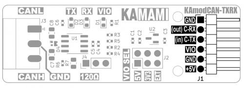
The functions of the individual pins are as follows:
- pin no. 1 - ground for control/power signals;
- pin no. 2 - C-RX, serial output for data read from the CAN bus;
- pin no. 3 - C-TX serial input for data that will be sent to the CAN bus;
- pin no. 4 - VIO, power input that specifies the voltage level on the C-RX and C-TX lines. The allowable range is 1.7...5 V;
- pin no. 5 - ground for control/power signals;
- pin no. 6 - main power input with a voltage of 5 V.
Selecting the voltage level of the serial interface
| Connector | Function |
|---|---|
| J2 - VIO SEL
Goldpin pins 2x3, 2.54 mm |
|
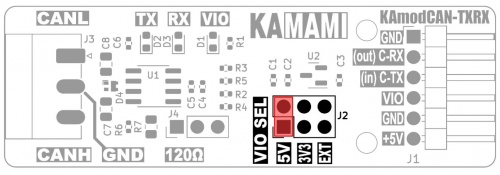
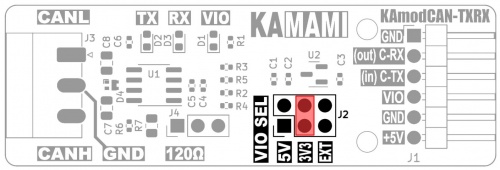
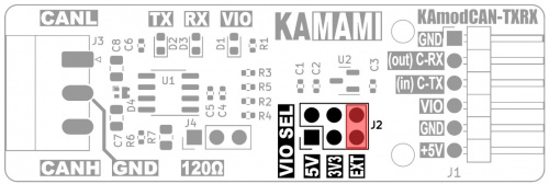
The VIO SEL connector allows you to select 1 of 3 voltage level values on the serial interface lines:
- position no. 1 marked "5 V" - shorting pins 1-2 means that the serial control interface is adapted to a voltage of 5 V, i.e. the supply voltage;
- position no. 2 marked "3V3" - shorting pins 3-4 means that the serial control interface is adapted to a voltage of 3.3 V, which is supplied from the voltage regulator integrated on the board;
- position no. 3 marked "EXT" - shorting pins 5-6 means that the serial control interface is adapted to the voltage supplied to the VIO pin of the J1 control connector.
1)
2)
3)
===== CAN bus connector=====
|- ! style="text-align: center;"|Connector ! style="text-align: center;"|Function |- | style="text-align: center;"|J3 - CAN Phoenix MC3,81 mm | style="text-align: left;"|
- CAN bus connector
|}
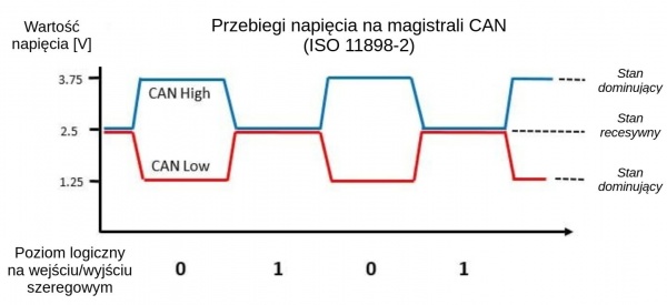
The CAN bus connector contains 3 contacts: CANL, CANH and GND. Their arrangement is well described on the module board. Each contact should be connected to the CAN bus according to the marking. The GND signal should be connected to the common ground of the power supply of devices connected by the CAN bus.
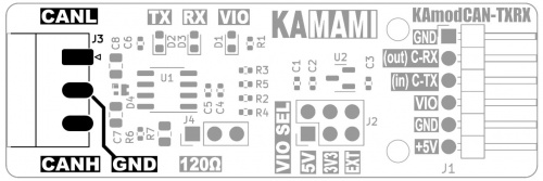
The voltage waveforms on the CAN bus are shown below drawing:
Connecting the terminating resistor
| Connector | Function |
|---|---|
| J4
1x3 goldpin pins, 2.54 mm |
|
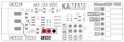
The devices in the CAN bus, as the name suggests, are connected in a bus topology. This is a single bus, without branches, in which two ends can be indicated. Each end of the bus should be equipped with a bus terminator - in the case of the CAN bus, this is a 120 Ω resistor. There is an appropriate resistor on the module board, which can be connected by setting the J4 jumper appropriately:
- shorting pins 1-2, as in the figure below, means that the 120 Ω terminating resistor is connected between the CANL and CANH lines;
- shorting pins 2-3, or removing the jumper disconnects the terminating resistor.
Power
| Connector | Function |
|---|---|
| J1
1x6 goldpin pins, 2.54 mm |
|
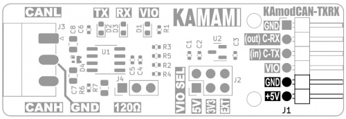
KAmod CAN-TXRX requires a DC power supply in the range of 4.5...5.5 V. The power supply should be connected to pins 5 and 6 of the J1 control connector:
- pin no. 5 - ground of control/power signals; :* pin no. 6 - main power input with a voltage of 5 V.
Signaling
| LEDs | Function |
|---|---|
| RX TX VIO |
|
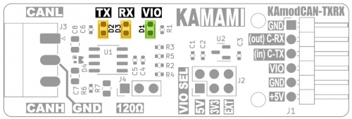
LEDs RX and TX indicate the active state – i.e. low logical state (dominant state on the CAN bus), respectively at the output and serial input – C-RX and C-TX. In the case of data transmission to the bus, both diodes – TX and RX will flash, because the data is simultaneously read by the transceiver.
At a voltage of VIO lower than 2.5 V, the VIO, RX, TX signaling diodes may light up very dimly, or may not light up at all. Despite this, the module will work properly.
Dimensions
The dimensions of the KAmod CAN-TXRX transceiver module are 61x20 mm, and the height is about 12 mm.
