KAmodESP32 ETH POE
From Kamamilabs.com - Wiki

Description
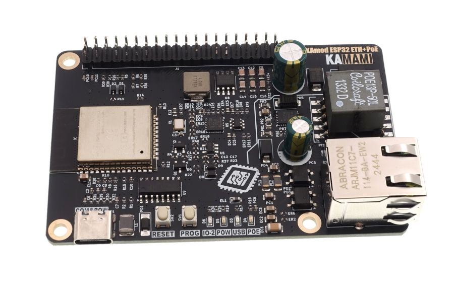
KAmodESP32 ETH POE - Evaluation board with ESP32-WROOM module connected to Ethernet interface and PoE power supply system
The KAmod ESP32 ETH+POE board contains ESP32-WROOM module enabling communication in 2.4 GHz Wi-Fi wireless network, however it has been connected to Ethernet wired interface with typical RJ45 connector. Programming ESP32 module is possible with USB-UART converter with USB-C connector. The board is complemented by PoE power supply system - Power over Ethernet, thanks to which power supply of the module can be supplied from internet installation. The board design corresponds to SBC of Raspberry Pi family - it has dimensions 81x56 mm, and on characteristic 40-pin connector all important I/O ports and supply voltages 5 V and 3.3 V, which can power additional components connected to the board, have been led out.
Basic features and parameters
- ESP32-WROOM module enabling communication in a Wi-Fi network in the 2.4 GHz band
- Ethernet interface based on the LAN8742 system (100/10 M; full/half duplex)
- Integrated UART-USB converter with USB-C connector enabling programming of the ESP32 system
- PoE power supply system, compatible with the IEEE 802.3af/at Class 0 standard
- Provides stabilized voltages of 5 V (+/-10%) and 3.3 V (+/-5%) with a total current of up to 1.5 A
- Overvoltage, overload and thermal protection
- All important I/O ports and supply voltages have been led out to the 40-pin connector in the Raspberry Pi standard
- Board dimensions: 85x56 mm, height approx. 20 mm
Standard Equipment
| Code | Description |
|---|---|
| KAmodESP32 ETH+POE | Assembled and launched module |
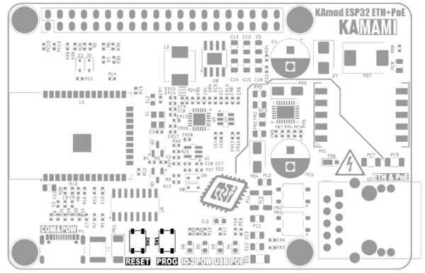
Electrical diagram
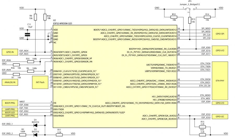
ESP32 module
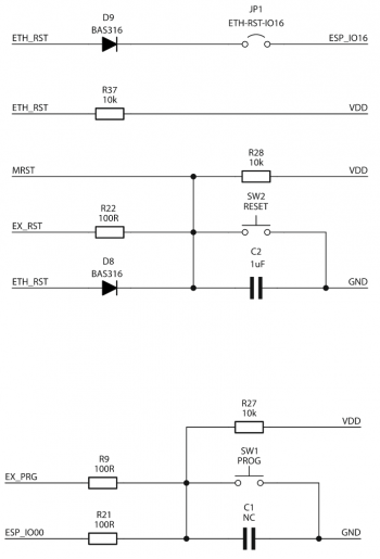
Elements responsible for reset and programming functions
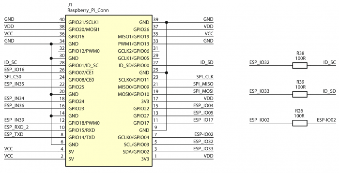
GPIO connector
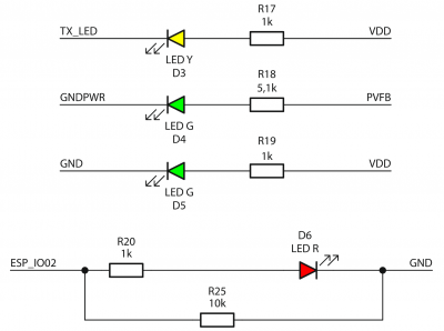
Indicator diodes
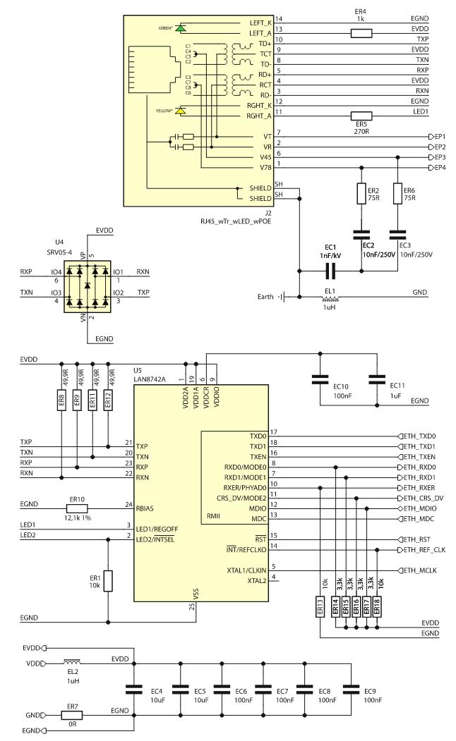
Ethernet interface
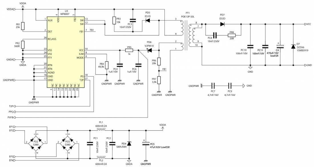
PoE power supply
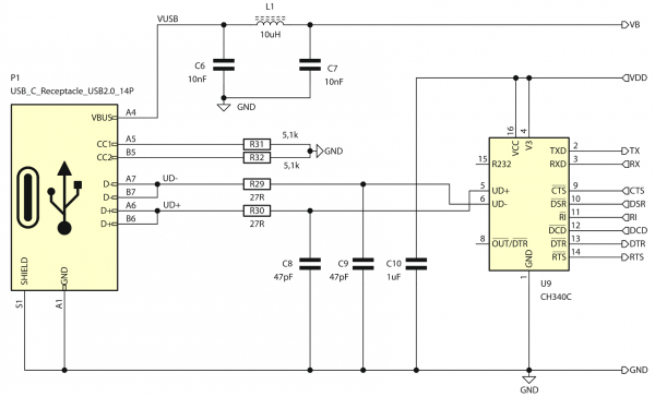
USB-UART interface
Source of the clocking signal

3.3V power block
Ethernet Interface
| Connector | Function |
|---|---|
| J2 – ETH & PoE
(RJ45) |
|
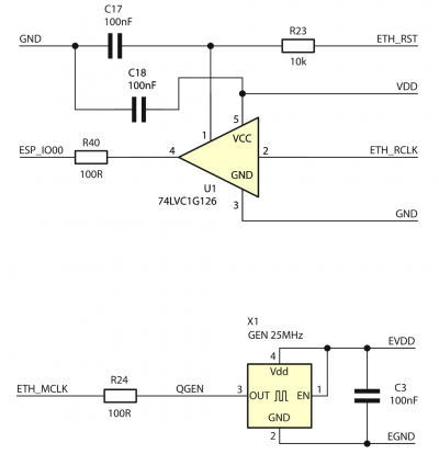
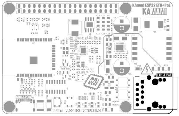
The KAmod ESP32 ETH+POE board implements a wired Ethernet interface with a classic RJ45 socket (J2). The LAN8742 chip, which is compatible with LAN8720 and supported in the Arduino environment, is used as the driver (PHY) of the Ethernet interface. It can operate at 100 Mb or 10 Mb in Full-Duplex or Half-Duplex mode.
The Ethernet driver is connected to the ESP32 module via the RMII interface (Reduced media-independent interface). The signal assignment is described in the table:
| RMII Signal | Direction | ESP32 Module Pinout |
|---|---|---|
|
TXD0 |
<- |
GPIO19 |
|
TXD1 |
<- |
GPIO22 |
|
TXEN |
<- |
GPIO21 |
|
RXD0 |
-> |
GPIO25 |
|
RXD1 |
-> |
GPIO26 |
|
CRS_DV |
-> |
GPIO27 |
|
MDIO |
<-> |
GPIO18 |
|
MDC |
<- |
GPIO23 |
|
REF_CLK |
-> |
GPIO0 |
|
RESET |
<- |
GPIO16 |
Power by PoE
| Connector | Function |
|---|---|
| J2 – ETH & PoE
(RJ45) |
|
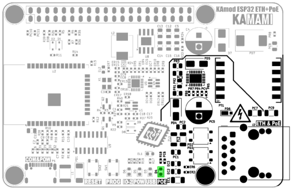
The ETH & PoE connector (J2) can be used to supply power to the evaluation board. The PoE power controller used is based on the MP8007 system, which is compatible with the IEEE 802.3af - Powered Devices Type-1 and IEEE 802.3at - Powered Devices Type-2 standards. The PoE power block is configured to operate in Class 0, which defines the device's power consumption in the range of 0.5...13 W.
Power supply using the PoE method is only possible in a compatible installation containing a PSE (Power Sourcing Equipments) device that meets the IEEE 802.3af/at standard, e.g. a PoE router. The correct operation of the PoE power block is indicated by the lighting of the POE diode (D4). During the operation of the PoE power supply unit, noise or a quiet squeak may be heard - this is a natural phenomenon caused by the operation of the switching power supply (SMPS).
When the KAmod ESP32 ETH+POE evaluation board is properly powered, stabilized voltages of approx. 5 V and 3.3 V are generated, available on the J1 pin connector. They can be used to power other modules connected to the evaluation board, but remember that the total current should not exceed 1.5 A.
In the PoE installation, voltages with values of up to 60 V occur. All activities performed in such installations using the KAmod ESP32 ETH+POE evaluation board should be performed with special caution and in compliance with safety rules.
USB Interface
| Connector | Function |
|---|---|
| P1 – COM&POW
(USB-C) |
|
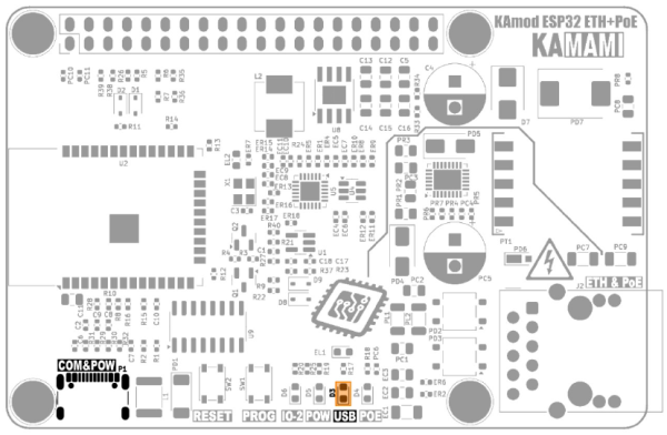
The P1 USB-C connector is connected to the CH340 type controller, which performs the functions of a USB-UART converter. The UART interface can be used in the target application, but it is also used to program the ESP32 module. The programming process can be completely automatic, because the CH340 controller controls the key pins of the ESP32 module (GPIO0 - Boot Select and EN - Chip Power-up).
The signal connections between CH340 and ESP32 are as follows:
| CH340 controller signal | ESP32 module pinout |
|---|---|
| TXD (data output) | GPIO03 (UART0 RXD) |
| RXD (data input) | GPIO01 (UART0 TXD) |
| DTR (transmission control output) | EN (Chip Power-up) |
| RTS (transmission control output) | GPIO0 (Boot Select) |
The TXD line is connected to an LED marked USB (D3), which signals the reception of data from the USB interface. If a USB-UART converter is used in the target application, it is necessary to ensure that the DTR and RTS lines remain unsupported (Handshaking: None).
The USB-C connector can be used as an alternative power input for the KAmod ESP32 ETH+POE board, but then the parameters of the power supply circuits will not be met. The voltage on the 5 V line will be lower and will be around 4.5 V; the voltage on the 3.3 V line should not change; the current efficiency of the 5 V and 3.3 V voltages may be much lower and will depend on the power supply used on the USB-C connector.
Reset and Programming Buttons
| Component | Function |
|---|---|
| SW1 Button – PROG |
|
| SW2 Button – RESET |
|
The RESET button allows you to restart the ESP32 module and, at the same time, the Ethernet interface controller. It is connected to the EN (Chip Power-up) line of the ESP32 module.
The PROG button allows you to enter the ESP32 module into programming mode. Then you should press the RESET button, then, while holding RESET, hold the PROG button and then release RESET, while still holding PROG for a moment. This functionality can be useful when for some reason the programming mode is not started automatically via the USB-UART converter.
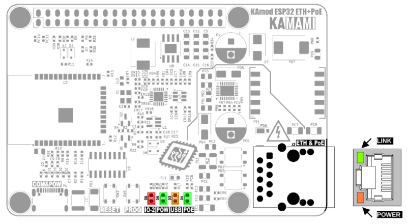
Signal lights
| Component | Function |
|---|---|
| D3 – USB |
|
| D4 – POE |
|
| D5 – POW |
|
| D6 – IO-2 |
|
There are 4 LEDs on the KAmod ESP32 ETH+POE board, which signal the operation of various components - according to the table above.
The D6 diode (LED IO-2) is connected to the GPIO2 pin of the ESP32 module. Its lighting up requires a programmatic setting of the high state on the GPIO2 pin.
The additional two signaling diodes are located on the J2 connector. The diode on the left (POWER) indicates the presence of the main supply voltage - voltage 3.3 V. The diode on the right (LINK) flashes to indicate the activity of the Ethernet interface.
GPIO connector in RPi standard
| Connector | Function |
|---|---|
| J1 – Goldpin 2x20 |
|
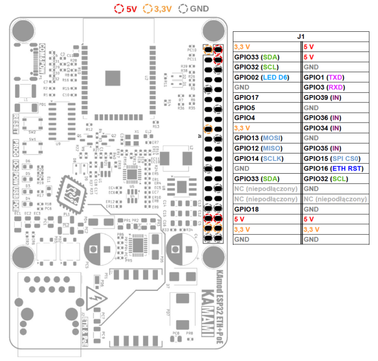
The Raspberry Pi standard GPIO connector (J1) contains 40 pins, to which the 5 V, 3.3 V, GND power lines and some GPIO pins of the ESP32 module are brought out. The UART (TXD, RXD), I2C (SDA, SCL) and SPI (MOSI, MISO, SCLK, CS0) interface pins have been arranged as they are in the Raspberry Pi family boards.
A detailed description of the pins and their functions is shown in the figure and table below:
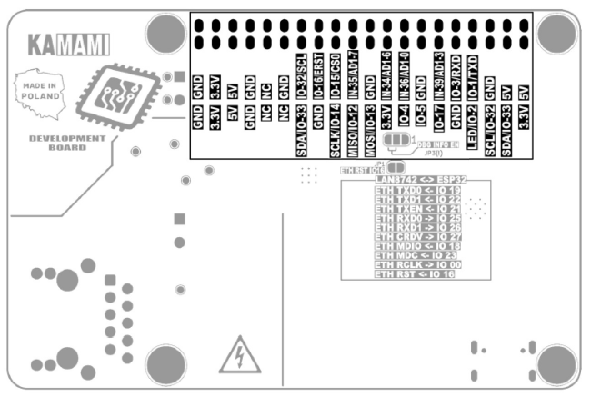
The description of the pins has also been marked on the bottom of the KAmod ESP32 board ETH+POE:
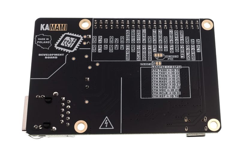
Notes on signals output to GPIO connector
- Ports GPIO 34, 35, 36 and 39 of the ESP32 module can only work as digital or analog inputs - they are marked with the symbol IN.
- Ports GPIO 34 and 35 are equipped with 10k pull-up resistors.
- Ports GPIO 36 and 39 are equipped with voltage dividers (100k/10k), thanks to which a maximum voltage of 35 V can be connected to them.
- Ports GPIO 32 and 33 are adapted to the functionality of the I2C bus and contain 2.2k pull-up resistors.
- Ports GPIO 1 and GPIO 3 act as a UART interface and are connected to the USB-UART converter module and in parallel to the GPIO J1 connector. The UART interface sends/reads data to/from the GPIO J2 connector and the USB-UART converter simultaneously.
- Ports GPIO5, GPIO12 and GPIO15 configure certain parameters of the ESP32 module. Their state is read at the moment of starting (restarting) the ESP32 module, which is why they are equipped with pull-up resistors: GPIO5 – pull-up, GPIO12 – pull-down, GPIO15 – pull-down. It is necessary to ensure that the logical level on these pins at the moment of starting (restarting) corresponds to the state forced by the pull-up/down resistors.
- Port GPIO16 has been connected to the Ethernet driver reset signal – LAN8742 system. Low state on this pin blocks the operation of the Ethernet interface.
Advanced Features
| Component | Function |
|---|---|
| JP1 – ETH RST IO16 |
|
| JP3 – DBG INFO EN |
|
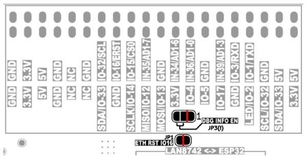
Jumpers JP1 and JP3 are located on the bottom side of the evaluation board.
JP1 – ETH RST IO16 is factory-shorted (copper path between pads) and provides a connection between the GPIO16 port of the ESP32 module and the RESET input of the Ethernet interface driver. To disconnect the GPIO16 port from the Ethernet driver reset signal, cut the surface of the board with a sharp tool – as indicated by the red line at JP1 in the drawing below. Reconnecting the reset signal is possible by applying a drop of solder, which will connect both pads of the JP1 jumper.
JP3 - DBG INFO EN is factory connected between the middle pad and pad number 1 (power supply ground) and causes the system messages, so-called Debugging Log, to be silenced. To enable sending system messages, cut the surface of the board with a sharp tool as indicated by the red line at JP3 in the drawing below and apply a drop of solder, which will connect the pads on the opposite side, pads 2-3 (up to a voltage of 3.3 V).
It is not allowed to connect pads 2-3 without first separating pads 1-2.
Dimensions
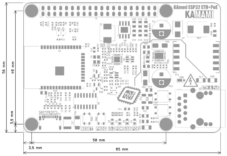
The dimensions of the KAmod ESP32 ETH+POE board are 85x56 mm. The maximum height is about 20 mm. The board has 4 mounting holes with a diameter of 3 mm, arranged similarly to the Raspberry Pi family boards.
Program testowy
Kod programu testowego znajduje się poniżej, można go skompilować w środowisku Arduino.
#include <ETH.h>
#include <WiFi.h>
/*
   * ETH_CLOCK_GPIO0_IN   - default: external clock from crystal oscillator
   * ETH_CLOCK_GPIO0_OUT  - 50MHz clock from internal APLL on GPIO0
   * ETH_CLOCK_GPIO16_OUT - 50MHz clock from internal APLL on GPIO16
   * ETH_CLOCK_GPIO17_OUT - 50MHz clock from internal APLL inverted on GPIO17
*/
#ifdef ETH_CLK_MODE
  #undef ETH_CLK_MODE
#endif
#define ETH_CLK_MODE    ETH_CLOCK_GPIO0_IN
// Pin# of the enable signal for the external crystal oscillator (-1 to disable for internal APLL source)
#define ETH_POWER_PIN   -1
// Type of the Ethernet PHY (LAN8720 or TLK110)
#define ETH_TYPE        ETH_PHY_LAN8720
// I²C-address of Ethernet PHY (0 or 1 for LAN8720, 31 for TLK110)
#define ETH_ADDR        0
// Pin# of the I²C clock signal for the Ethernet PHY
#define ETH_MDC_PIN     23
// Pin# of the I²C IO signal for the Ethernet PHY
#define ETH_MDIO_PIN    18

#define ETH_RESET     16

#define LED_PIN       2

static bool eth_connected = false;

WiFiServer server(80);

// Select the IP address according to your local network
IPAddress myIP(10, 1, 0, 182);
IPAddress myGW(10, 1, 0, 252);
IPAddress mySN(255, 255, 0, 0);
IPAddress myDNS(8, 8, 8, 8);

void myEvent(WiFiEvent_t event) {
  switch (event) {
    case ARDUINO_EVENT_ETH_START:
      Serial.println("ETH Started");
      ETH.setHostname("esp32-ethernet");
      break;
    case ARDUINO_EVENT_ETH_CONNECTED:
      Serial.println("ETH Connected");
      break;
    case ARDUINO_EVENT_ETH_GOT_IP:
      //Serial.println("ETH Got IP");
      //Serial.println(ETH);
      Serial.print("ETH MAC: ");
      Serial.print(ETH.macAddress());
      Serial.print(", IPv4: ");
      Serial.print(ETH.localIP());
      if (ETH.fullDuplex()) {
        Serial.print(", FULL_DUPLEX");
      }
      Serial.print(", ");
      Serial.print(ETH.linkSpeed());
      Serial.println("Mbps");
      eth_connected = true;
      break;
    case ARDUINO_EVENT_ETH_LOST_IP:
      Serial.println("ETH Lost IP");
      eth_connected = false;
      break;
    case ARDUINO_EVENT_ETH_DISCONNECTED:
      Serial.println("ETH Disconnected");
      eth_connected = false;
      break;
    case ARDUINO_EVENT_ETH_STOP:
      Serial.println("ETH Stopped");
      eth_connected = false;
      break;
    default:
      break;
  }
}

void setup() {
  //ETH Reset assert
  pinMode(ETH_RESET, OUTPUT);
  digitalWrite(ETH_RESET, LOW);

  pinMode(LED_PIN, OUTPUT);
  for(int i=0; i<5; i++){
    digitalWrite(LED_PIN, HIGH);
    delay(200);
    digitalWrite(LED_PIN, LOW);
    delay(200);
  }

  //ETH Reset deassert
  digitalWrite(ETH_RESET, HIGH);
  delay(200);

  //Serial - start
  Serial.begin(115200);

  WiFi.onEvent(myEvent);
  ETH.begin(ETH_TYPE, ETH_ADDR,
            ETH_MDC_PIN, ETH_MDIO_PIN,
            ETH_POWER_PIN, ETH_CLK_MODE);
  //ETH.config(myIP, myGW, mySN, myDNS);

  while (!ETH.connected()){}
  server.begin();
}

void loop() {
  // listen for incoming clients
  WiFiClient client = server.available();

  if (client) {
    Serial.println("********New Client********");

    String currentLine = "";

    while (client.connected()) {
      if (client.available()) {
        char c = client.read();
        //Serial.write(c);
        if (c == '\n') {

          if (currentLine.length() == 0) {
            client.println("HTTP/1.1 200 OK");
            client.println("Content-type:text/html");
            client.println();
            client.print("<H2>Click <a href=\"/H\">here</a> to turn ON the LED.<br>");
            client.print("Click <a href=\"/L\">here</a> to turn OFF the LED.<br>");
            client.print("Click <a href=\"/SEND\">here</a> to write to Serial (USB).<br></H2>");
            client.println();
            break;
          } else {
            currentLine = "";
          }
        } else if (c != '\r') {
          currentLine += c;
        }

        //if (currentLine.endsWith("GET /H")) {
        if (currentLine.indexOf("GET /H") >= 0) {
          digitalWrite(LED_PIN, HIGH);
        }
        //if (currentLine.endsWith("GET /L")) {
        if (currentLine.indexOf("GET /L") >= 0) {
          digitalWrite(LED_PIN, LOW);
        }
        if (currentLine.endsWith("GET /SEND")) {
          Serial.println("\r\nHELLO - you send message via Serial(USB)");
        }
      }
    }

    delay(10);
    client.stop();
    Serial.println("********Client Disconnected********");
  }
}
Program testowy konfiguruje port GPIO2 jako wyjście sterujące diodą LED (D6) i sygnalizuje rozpoczęcie działania kilkoma mignięciami. Następnie uruchamia sprzętowy interfejs UART i konfiguruje go do pracy jako interfejs szeregowy połączony do konwertera UART-USB. Dzięki temu można monitorować działanie płytki w dowolnym programie typu terminal (Serial Monitor).
#define LED_PIN 2
pinMode(LED_PIN, OUTPUT);
for(int i=0; i<5; i++){
digitalWrite(LED_PIN, HIGH);
delay(200);
digitalWrite(LED_PIN, LOW);
delay(200);
}
//Serial - start
Serial.begin(115200);
Przygotowanie do pracy drivera interfejsu Ethernet – układu LAN8742, wymaga dołączenia biblioteki ETH.h oraz zdefiniowania funkcji wyprowadzeń. Układ LAN8742 jest kompatybilny z układem LAN8720, który z kolei jest wspierany w środowisku Arduino.
#include <ETH.h>
/*
* ETH_CLOCK_GPIO0_IN - default: external clock from crystal oscillator
* ETH_CLOCK_GPIO0_OUT - 50MHz clock from internal APLL on GPIO0
* ETH_CLOCK_GPIO16_OUT - 50MHz clock from internal APLL on GPIO16
* ETH_CLOCK_GPIO17_OUT - 50MHz clock from internal APLL inverted on GPIO17
*/
#ifdef ETH_CLK_MODE
#undef ETH_CLK_MODE
#endif
#define ETH_CLK_MODE ETH_CLOCK_GPIO0_IN
// Pin# of the enable signal for the external crystal oscillator (-1 to disable for internal APLL source)
#define ETH_POWER_PIN -1
// Type of the Ethernet PHY (LAN8720 or TLK110)
#define ETH_TYPE ETH_PHY_LAN8720
// I²C-address of Ethernet PHY (0 or 1 for LAN8720, 31 for TLK110)
#define ETH_ADDR 0
// Pin# of the I²C clock signal for the Ethernet PHY
#define ETH_MDC_PIN 23
// Pin# of the I²C IO signal for the Ethernet PHY
#define ETH_MDIO_PIN 18
#define ETH_RESET 16
//ETH Reset assert
pinMode(ETH_RESET, OUTPUT);
digitalWrite(ETH_RESET, LOW);
...
//ETH Reset deassert
digitalWrite(ETH_RESET, HIGH);
delay(200);
Teraz można uruchomić interfejs oraz serwer www:
WiFiServer server(80);
ETH.begin(ETH_TYPE, ETH_ADDR,
ETH_MDC_PIN, ETH_MDIO_PIN,
ETH_POWER_PIN, ETH_CLK_MODE);
...
while (!ETH.connected()){}
server.begin();
Po uruchomieniu programu testowego zostanie uruchomiony serwer www z bardzo prostą stroną internetową, która umożliwia sterowanie diodą LED D6 oraz wysłanie komunikatu poprzez port szeregowy:

Adres IP, który zostanie przydzielony serwerowi www w sieci LAN można odczytać z komunikatów wysyłanych przez port szeregowy:

Adres IP można również określić w programie, należy wtedy określić cztery parametry:
IPAddress myIP(10, 1, 0, 182);
IPAddress myGW(10, 1, 0, 252);
IPAddress mySN(255, 255, 0, 0);
IPAddress myDNS(8, 8, 8, 8);
a następnie wpisać polecenie:
ETH.config(myIP, myGW, mySN, myDNS);
przed linią:
server.begin();