KAmduino UNO V2
From Kamamilabs.com - Wiki

Description
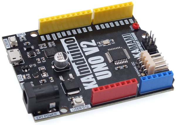
KAmduino UNO V2 is a development board with functionality and dimensions typical of Arduino UNO. Thanks to the built-in ATmega328P microcontroller and the CP2102 chip, board can be programmed via USB connector with using Arduino software (IDE).
Basic features and parameters
- ATmega328P microcontroller from ATMEL
- 20 GPIO pins on connectors (including 6 lines with PWM mode)
- Uploaded Arduino bootloader
- MicroUSB-B connector for programming and data exchange
- Possibility of power supply via DC-JACK socket (2.1x5.5) by voltage in range 7…15V
- Protection against reverse voltage polarity on DC connector
- Possibility of power via USB connector
- Connectors compatible with Arduino UNO standard
- On-board User LED and LEDs signalling transmission from/to computer
- On-board User button
- On-board microcontroller reset-button
- USB connector protected against electrostatic discharge
- Possibility of expanding the functionality by using additional shields
- KAMAMI standard I2C connector for connecting additional modules
- Mounting holes with a diameter of 3mm
- Module dimensions: 69mm x 55mm x 14mm
Standard equipment
| Code | Description |
|---|---|
| KAmduino UNO V2 | Assembled and launched module |
Electrical schematics
AVR ATmega328P microcontroller
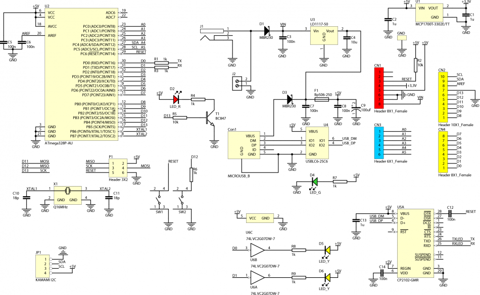
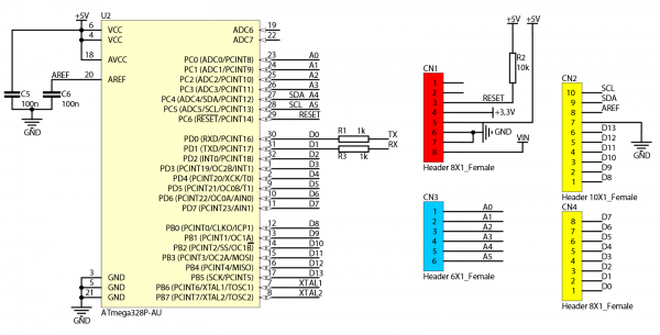
Embedded AVR ATmega328P microcontroller from ATMEL allow for using a board in development application, in which is required large Flash memory (32kB), RAM (2kB) or a large number of PWM signals (6 channels). Microcontroller can be running with frequency up to 16MHz. Uploaded Arduino bootloader make possible programming via USB connector with using Arduino IDE.
Power supply
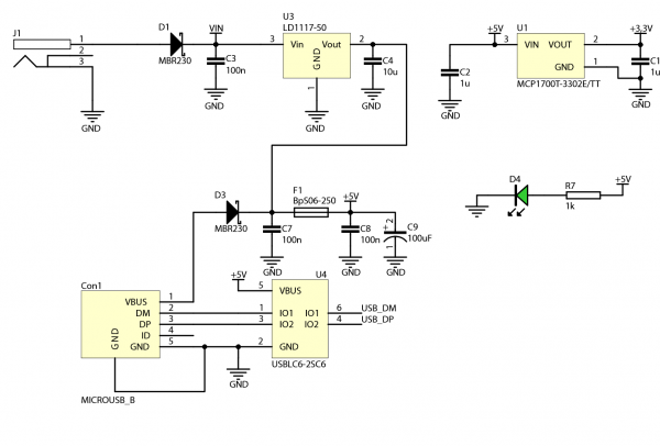
KAmduino UNO V2 board can be supply via both USB connector and external power supplier with connector 2.1x5.5. The board has embedded protection circuit against reverse voltage polarity, as well as overcurrent protection of USB connector (polymer fuse). Correct power supply of development board is signalled by PWR green LED.
USB communication
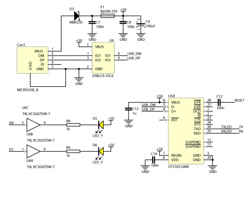
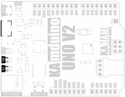
KAmdunio UNO board has embedded USB connector. Connector can be used to communication with computer and board programming. USB connector is protected against electrostatic discharges. Thanks to this, board is resistant to the appearance of accidental electrostatic discharge and after-effects. Transmission both from and to computer is signalized by two yellow RX and TX LEDs. Board is installed on the computer as Serial Port (COM), thanks to cooperate with Arduino IDE, as well as with each terminal. Using of CP2102 allow to reset of microcontroller from computer level in every moment.
Connector compatible with Arduino UNO
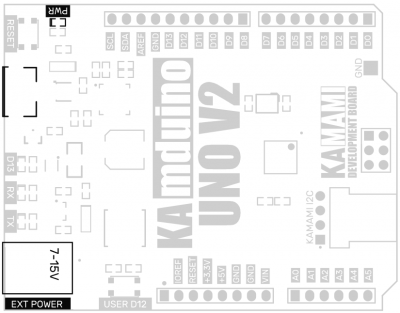
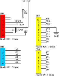
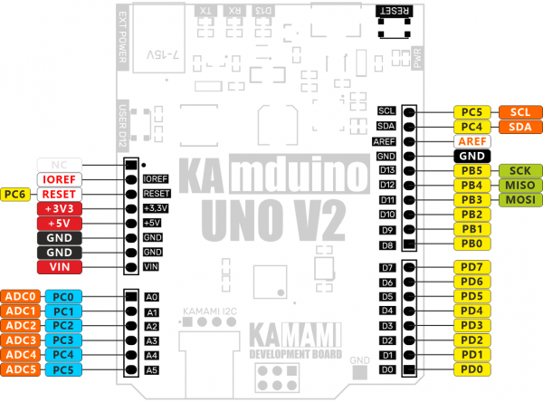
Board is equipped with female connectors compatible with Arduino UNO standard. Thanks to this, it is possible to using additional modules (shields). On connectors, except all I/O microcontroller pins, are available power supply 5V and 3.3V, as well as RESET signal (connected parallel with button) and reference voltage of ADC converter.
ISP connector
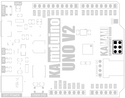
KAmduino UNO V2 board has also connector for programming of ATmega328P microcontroller via ISP interface. By using programmer with ISP interface, microcontroller can be programmed without Arduino bootloader (bootloader will be deleted!).

I2C bus connector
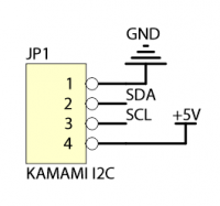
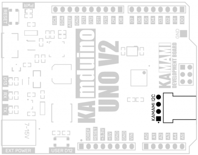
KAmduino UNO V2 is equipped with a KAMAMI I2C connector enabling the connection of external systems operating on the I2c bus. The SDA (PC4/A4) and SCL (PC5/A5) lines are not pulled up to the supply voltage, the pull-up resistors must be connected externally.
User LED
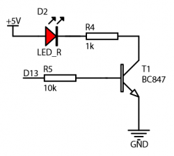
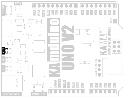
On KAmduino UNO V2 board is placed user LED (marked as "13"). It is controlled with MOSFET transistor with N-channel, connected to PB7 pin of microcontroller (output 13). Thanks of using the transistor, line is not loaded. It can be still using externally.
User button
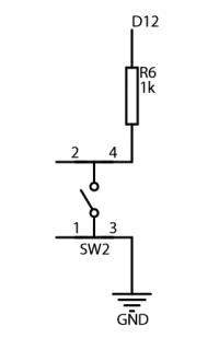
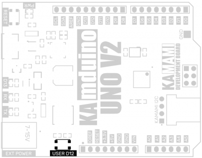
The KAmduino UNO V2 board is equipped with a user button (marked as "USER D12"), it is connected to the PB.4 line of the microcontroller (output 12)
