Difference between revisions of "KAmodLSM303"
Anna Kubacka (talk | contribs) |
|||
| (5 intermediate revisions by 3 users not shown) | |||
| Line 1: | Line 1: | ||
__jzpdf__ | __jzpdf__ | ||
| − | ====== | + | ====== Description ====== |
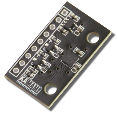
| − | [https://kamami.pl/kamod-kamami/557717-kamodlsm303-modul-akcelerometru-magnetometru-z-ukladem-lsm303d.html KAmodLSM303] | + | [https://kamami.pl/kamod-kamami/557717-kamodlsm303-modul-akcelerometru-magnetometru-z-ukladem-lsm303d.html KAmodLSM303] is a module with MEMS LSM303D type. Chip has a digital output (with using I2C or SPI interface) and allow to make a measurement of acceleration and magnetic field value in three axis. Thanks to programmable interrupt outputs, it is possible e.g. wake up a microcontroller after free fall detection or object movement. Module can be used in system with power supply 2.5 - 5.5V. |
| − | + | ||
<center> | <center> | ||
| − | [[ | + | [[File:KAmodLSM303_moduł.png|none|400px|thumb|center]] |
</center> | </center> | ||
| − | ===== | + | ===== Basic features and parameters ===== |
| − | * | + | *LMS303D chip (accelerometer and magnetometer) from STMicroelectronics |
| − | * | + | *Measurement range of accelerometer: ±2 / ±4 / ±6 / ±8 / ±16g |
| − | * | + | *Measurement range of magnetometer: ±2 / ±4 / ±8 / ±12 Gauss |
| − | * | + | *Power supply voltage: 2.5V - 5.5V |
| − | * | + | *Sleep mode / Low power mode |
| − | * | + | *Communication interface: SPI / I2C |
| − | * | + | *Embedded voltage regulator and logic level translator (SDA and SCL lines) |
| − | * | + | *Programmable interrupt generator (by free fall, movement detection or magnetic field detection) |
| − | * | + | *Place for soldering of pin header |
| − | * | + | *Mounting holes 3mm |
| − | * | + | *Module size (without connector): 27mm x 15mm x 3mm |
| − | ===== | + | ===== Standard equipment ===== |
<center> | <center> | ||
{| class="wikitable" style="width: 1000px;" | {| class="wikitable" style="width: 1000px;" | ||
|- | |- | ||
| − | ! style="text-align: center;"| | + | ! style="text-align: center;"|Code |
| − | ! style="text-align: center;"| | + | ! style="text-align: center;"|Description |
|- | |- | ||
| style="text-align: center;"|<b>KAmodLSM303</b> | | style="text-align: center;"|<b>KAmodLSM303</b> | ||
| style="text-align: center;"| | | style="text-align: center;"| | ||
| − | * | + | *Assembled and launched module |
| − | * | + | *Pin header (male and angle) for soldering |
|} | |} | ||
</center> | </center> | ||
| − | ===== | + | ===== Electrical schematic ===== |
<center> | <center> | ||
| − | [[ | + | [[File:KAmodLSM303_schemat.png|none|800px|thumb|center]] |
</center> | </center> | ||
| − | ===== | + | ===== Outputs description ===== |
<center> | <center> | ||
{| class="wikitable" style="width: 1000px;" | {| class="wikitable" style="width: 1000px;" | ||
|- | |- | ||
| − | ! style="text-align: center;" rowspan="10"| [[ | + | ! style="text-align: center;" rowspan="10"| [[File:KAmodLSM303 obrys PCB.png|center|200px]] |
! style="text-align: center;"|JP1 | ! style="text-align: center;"|JP1 | ||
! style="text-align: center;"|I2C | ! style="text-align: center;"|I2C | ||
| Line 50: | Line 50: | ||
|- | |- | ||
| style="text-align: center;"|+3.3V | | style="text-align: center;"|+3.3V | ||
| − | | rowspan="3" colspan="3" style="text-align: center;" | | + | | rowspan="3" colspan="3" style="text-align: center;" |Module power supply |
|- | |- | ||
| style="text-align: center;"|+VIN | | style="text-align: center;"|+VIN | ||
| Line 77: | Line 77: | ||
|- | |- | ||
| style="text-align: center;"|INT2 | | style="text-align: center;"|INT2 | ||
| − | | colspan="3" style="text-align: center;" | | + | | colspan="3" style="text-align: center;" |Interrupt 2 output |
|- | |- | ||
| style="text-align: center;"|INT1 | | style="text-align: center;"|INT1 | ||
| − | | colspan="3" style="text-align: center;" | | + | | colspan="3" style="text-align: center;" |Interrupt 1 output |
|} | |} | ||
</center> | </center> | ||
| − | ===== | + | =====External links ===== |
| − | *[http://download.kamami.pl/p557717-KAmodLSM303D_LSM303_DS.pdf | + | *[http://download.kamami.pl/p557717-KAmodLSM303D_LSM303_DS.pdf LSM303D chip datasheet] |
| − | |||
| − | |||
| − | |||
Latest revision as of 10:19, 23 September 2020

Contents
Description
KAmodLSM303 is a module with MEMS LSM303D type. Chip has a digital output (with using I2C or SPI interface) and allow to make a measurement of acceleration and magnetic field value in three axis. Thanks to programmable interrupt outputs, it is possible e.g. wake up a microcontroller after free fall detection or object movement. Module can be used in system with power supply 2.5 - 5.5V.
Basic features and parameters
- LMS303D chip (accelerometer and magnetometer) from STMicroelectronics
- Measurement range of accelerometer: ±2 / ±4 / ±6 / ±8 / ±16g
- Measurement range of magnetometer: ±2 / ±4 / ±8 / ±12 Gauss
- Power supply voltage: 2.5V - 5.5V
- Sleep mode / Low power mode
- Communication interface: SPI / I2C
- Embedded voltage regulator and logic level translator (SDA and SCL lines)
- Programmable interrupt generator (by free fall, movement detection or magnetic field detection)
- Place for soldering of pin header
- Mounting holes 3mm
- Module size (without connector): 27mm x 15mm x 3mm
Standard equipment
| Code | Description |
|---|---|
| KAmodLSM303 |
|
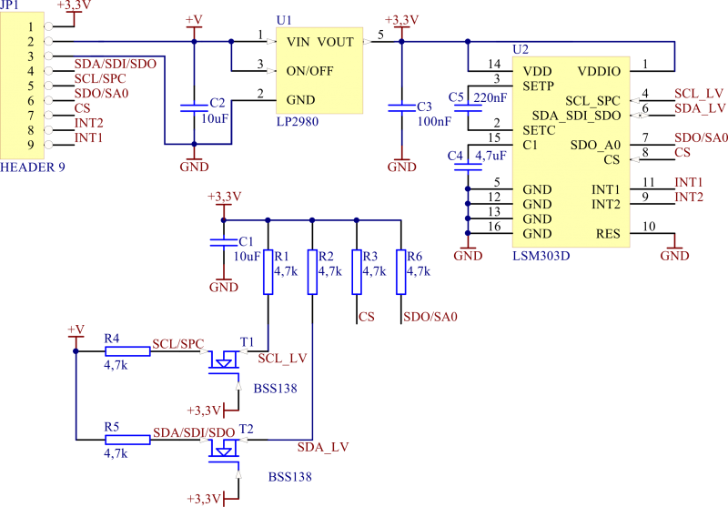
Electrical schematic
Outputs description
| JP1 | I2C | SPI 3-wire | SPI 4-wire | |
|---|---|---|---|---|
| +3.3V | Module power supply | |||
| +VIN | ||||
| GND | ||||
| SDA/SDI/SDO | SDA | SDI/SDO | SDI | |
| SCL/SPC | SCL | SPC | SPC | |
| SDO/SA0 | SA0 | - | SDO | |
| CS | CS | CS | CS | |
| INT2 | Interrupt 2 output | |||
| INT1 | Interrupt 1 output | |||


