KAmodMMA8451Q

Contents
Description
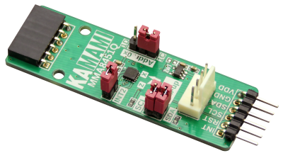
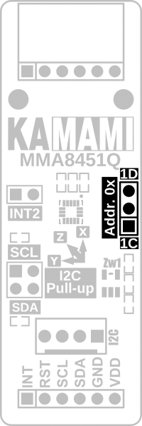
KAmodMMA8451Q is a module with the NXP MMA8451Q triaxial accelerometer. The board is equipped with a Pmod I2C standard connector and a KAMAMI connector, that allows easy connection of the module to the evaluation kits. Due to its small dimensions, the product can be used in many development projects, while the Pmod loop connector allows to connect the boards in the series.
Basic features and parameters
- MMA8451Q chip from NXP
- Acceleration measurement in the range of ±2g/±4g/±8g
- Frequency of measurement: from 1.56Hz to 800Hz
- Noise level: 99μg/√ Hz
- Orientation detection with programmable hysteresis
- Embedded self-test function
- I2C bus
- Programmable interrupt output
- Possibility to choose the chip address (0x1C or 0x1D)
- Connector compatible with the Pmod standard, allows serial connection of Pmod I2C modules
- The connector complies with the KAMAMI standard
- Embedded jumpers activating pull-up on I2C bus lines
- Embedded jumper connecting the INT line of the chip to the INT line of Pmod connectors
- Embedded I2C address selector
- Possibility to supply voltage from 2.1...3.6V through Pmod connector and 2.1V...5.5V through KAMAMI connector
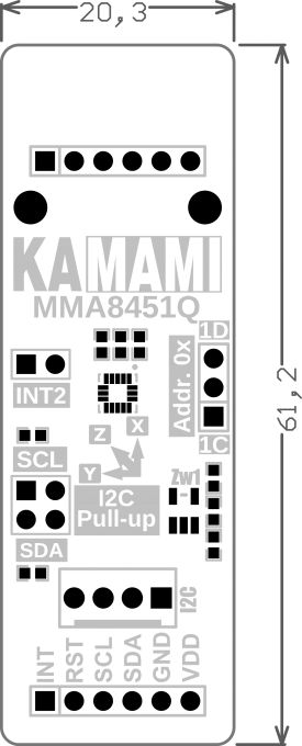
- Mounting holes with a diameter of 2.5mm
- Dimensions: 61.2mm x 20.3mm x 10mm
Standard equipment
| Code | Description |
|---|---|
| KAmodMMA8451Q |
|
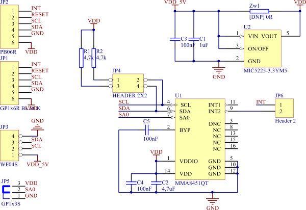
Electrical schematics
Output description - Pmod standard connector
| JP1 male connector) | JP2 (female connector) | Function | |
|---|---|---|---|
| VDD | VDD | Power supply of module (max. 3,6 V) | |
| GND | GND | ||
| SDA | SDA | Data line of I2C bus | |
| SCL | SCL | Clock line of I2C bus | |
| RST | RST | - | |
| INT | INT | Interrupt line INT2 |
Output description – KAMAMI standard connector
| Pin number | Function | |
|---|---|---|
| 1 (VDD_5V) | Power supply of module (max. 5,5 V) | |
| 2 (SCL) | Clock line of I2C bus | |
| 3 (SDA) | Data line of I2C bus | |
| 4 (GND) | Ground |
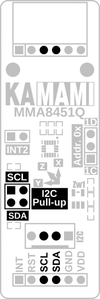
I2C bus lines
The KAmodMMA8451Q module is equipped with jumpers allowing to connect pull-up resistors to the positive power pole to the I2C bus line. The jumpers give the possibility of independent enabled of the pull-up for the SDA and SCL lines.
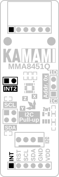
Interrupt line INT2
The KAmodMMA8451Q module has been equipped with a jumper enabling connection of the INT2 interrupt output line to the Pmod compatible connector. Thanks to the possibility of disconnecting the MMA8451Q interrupt line from Pmod connectors, the user does not have to worry about the consequences of possible conflicts resulting from the connection of Pmod-compatible module modules with different logic states.
I2C address
The KAmodMMA8451Q module has been equipped with the function of selecting one of the two I2C bus addresses for the MMA8451Q chip. The jumper "Addr. 0x" in position "1D" causes that the integrated circuit will be represented by bus address 0x1D (HEX), and in position "1C" - 0x1C (HEX).
