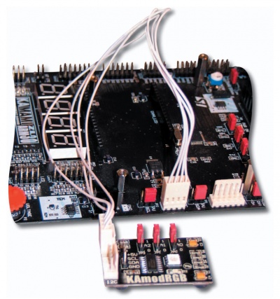
KAmodRGB
From Kamamilabs.com - Wiki

Description
KAmodRGB module make possible to equip any digital system with an I2C interface in an autonomous, 4-channel LED driver. It can be used to control LED RGB and more and more popular used RGBA.
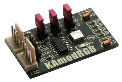
Basic parameters
- 4-channel LED driver PCA9633 from NXP
- I2C interface (also Fm+)
- 5-channel PWM waveform generator with 8-bit resolution in each channel
- programmable PWM frequency 190Hz or 0.09...24Hz
- PWM coefficient regulation range 0...99.6%
- configurable LED control outputs open drain or totem-field type
- load capacity up to 25mA
- 8 I2C addresses
- I/O lines with 5V tolerant
- supply voltage 2.3...5.5 VDC (5V recommended)
- built-in RGB LED and additional LED
- I2C connector in KAMAMI standard (available in many development kits)
Standard equipment
| Code | Description |
|---|---|
| KAmodRGB |
|
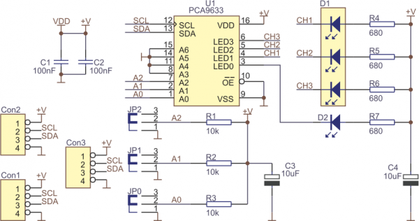
Schematic
View of board
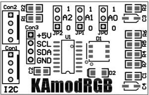
Output description
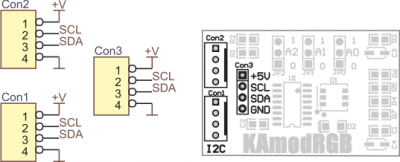
I2C interface (lines without pulling resistors up to +V!) is connected to connectors Con1, Con2 and Con3 as shown in the figure below.
Address lines
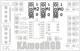
Address lines A2, A1, A0 of the PCA9633 chip were available on jumpers of the KAmodRGB module. The other address lines A3...A6 are connected to the ground. The lines A2, A1 and A0 have been pulled up to the power supply, which causes the default base address of the module to be 0000111. It can be changed in the range from 0000000 to 0000111 by setting jumpers for contacts 1-2 of JP0, JP1 and JP2.
Connection LED to PCA9633 controller
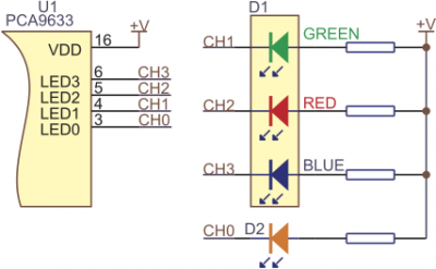
KAmodRGB module uses one RGB diode (D1) and one single-color diode (D2). They are connected to PCA9633 controller as shown on the figure.
Module connection
The KAmodRGB module is equipped with Con1 and Con2 connectors that make possible to connect direct to KAMAMI boards equipped with dedicated I2C connectors (i.a. STM32Butterfly, ZL30ARM, ZL15AVR, ZL16AVR, ZL5PIC, etc.). You can use the cable designated CAB_HU04-30 from the offer of KAMAMI.pl for this purpose.
