ADuCino 360
From Kamamilabs.com - Wiki

Description
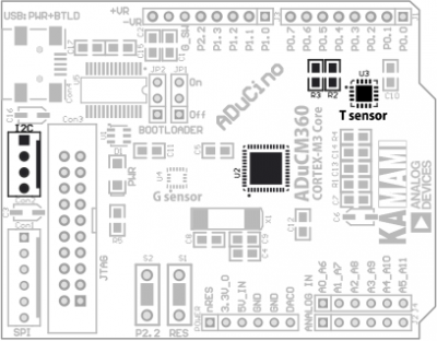
ADuCino is an inexpensive evaluation board with ARM Cortex-M3 core-based ADuCM360 or ADuCM361 microcontroller. The board has a complete range of peripherals, including ISP/UART programming interface (based on ADI’s bootloader), SWD connector, I2C channel, two SPI channels, UART with virtual USB COM port, digital temperature sensor, MEMS 3D accelerometer, switches, etc. ADuCino is mechanically compatible with Arudino system and shields.
Overview
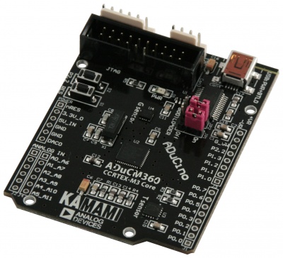
ADuCino360 is evaluation board with Analog Devices ADuCM360/361 microcontroller (Cortex-M3 core). It is mechanically compatible with Arduino and has built-in USB flash programmer, MEMS accelerometer and digital temperature sensor.
Hardware features
- ADuCM360 microcontroller (Cortex-M3 @16 MHz, 128kB Flash, 8kB SRAM, 2xADC 24-bit, 12-bit DAC, UART, I2C, 2xSPI, 16-bit PWM controller, 19xGPIOs)
- ADXL362 MEMS 3D accelerometer (SPI)
- ADT7420 temperature sensor (I2C)
- USB interface (Flash ISP programming and virtual serial port), two microswitches (reset and user), mechanically compatible with Arduino system
- I2C and SPI connectors (KAmod standard)
- JTAG/SWD connector,
- GPIOs and ADCin lines available on 2.54mm pins
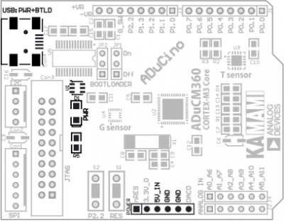
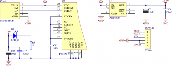
- USB or external (POWER connector) +5V power supply
Package contents
| Code | Description |
|---|---|
| ADuCino360 |
|
Schematic
Power supply
Microswitches
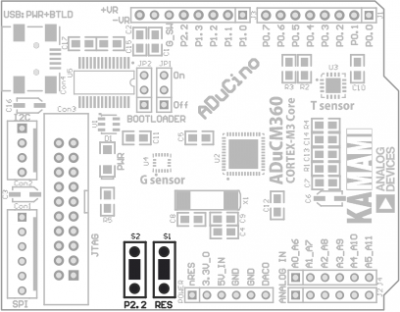
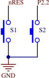
ADuCino360 board is equipped with two microswitches:
- S1 – reset button
- S2 – connected to GPIO P2.2 line. It can be used in user applications, it can also activate bootloader
3D accelometer
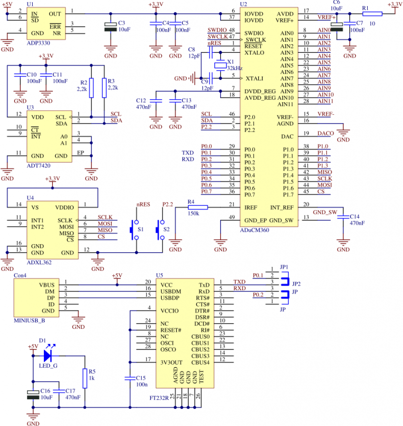
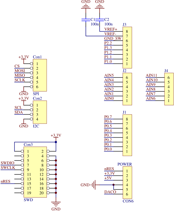
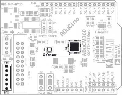
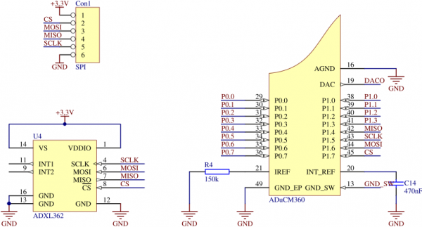
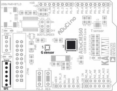
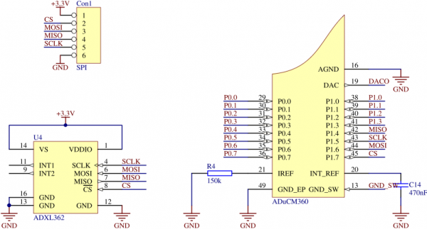
ADuCino360 board is equipped with ADXL362 3D digital accelerometer (U4) with SPI interface. It is connected to ADuCM360 SPI0 interface. SPI0 lines are also available on Con1 connector (KAmod standard).
Temperature sensor
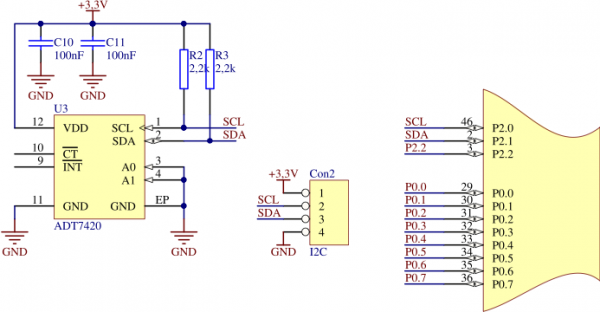
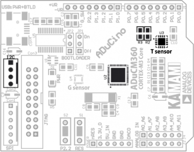
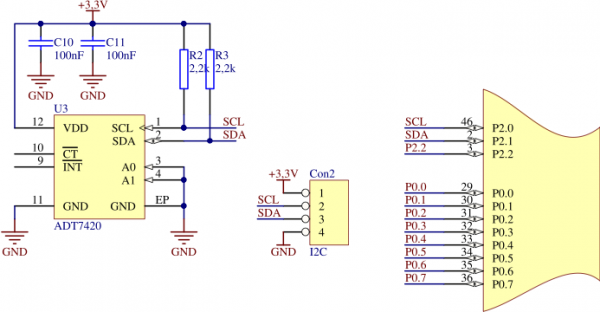
ADuCino360 board is equipped with ADT7420 digital temperature sensor with I2C interface. Sensor is connected to ADuCM360 I2C interface, its lines have pull-up resistors (R2, R3). Sensor I2C address is 0x48.
USB<->UART converter
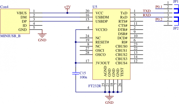
ADuCino360 board is equipped with bidirectional USB<->UART converter (U5). It can be used in user applications to communicate with PC. It is also used by bootloader for Flash programming. To connect USB<->UART converter to P0.1 and P0.2 microcontroller pins put JP1 and JP2 jumpers in „On” position
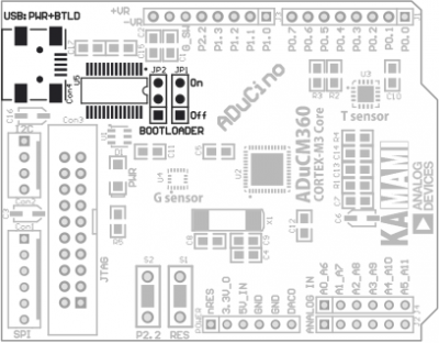
| ADuCino360 board’s microcontroller has built-in bootloader (On-Chip Kernel), it lets Flash memory to be programmed with data received from UART interface. To activate bootloader press S1 button (reset) while holding S2 button. CM3WSD software is needed to perform flash programming, it is available at Analog Devices website. |
Interface SWD
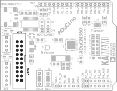
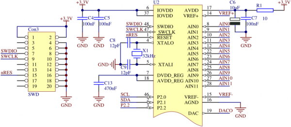
ADuCM360 microcontrollers have SWD interface (Single Wire Debugging), designed for debugging and flash programming. ADuCino360 Con3 connector has standard SWD/JTAG pinout, therefore it is compatible with most popular debuggers: uLINK, J-Link etc.
GPIO and ADCin connectors
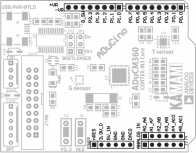
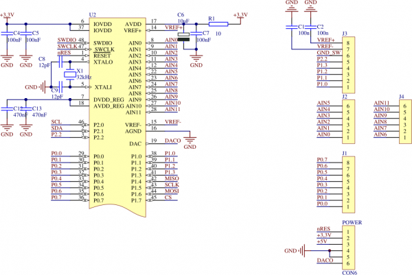
ADuCM360 microcontroller digital GPIO lines and analog inputs are available on 2.54mm gold-pin connector, its pinout is shown on picture below.
SPI connector
ADuCM360 SPI0 interface is available on Con1 connector (KAmod standard). Note that SPI0 lines are also connected to built-in accelerometer.
I2C connector
ADuCM360 I2C interface is available on Con2 connector (KAmod standard). Note that these lines are also connected to built-in temperature sensor.
