KAmod0029 - SMD Soldering Learning Kit
From Kamamilabs.com - Wiki

Description
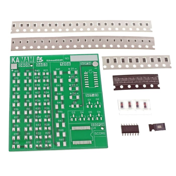
KAmod0029 - SMD Soldering Learning Kit - 0603, 0805, 1206
The SMD soldering kit is designed for beginners in electronics who want to master the skills of surface mounting SMD components. It is an excellent educational gift, allowing you to gain invaluable experience in practical assembly of components. The user can freely experiment, choosing the right tip, flux and temperature, learning by trial and error what settings are most effective for different components. The high-quality printed circuit board with solder mask included in the kit serves as a basis for mounting components. The kit includes: resistors in SMD packages in sizes 0805 (20 pieces), 0603 (20 pieces) and 1206 (9 pieces); 4 diodes in SMD SOD80 package; 1 LED 0805 diode; 6 transistors in SOT-23 package; and 1 SMD integrated circuit in SOP14 package with a pitch of 1.27 mm. This versatile educational tool is the key to practical knowledge of the world of SMD soldering.
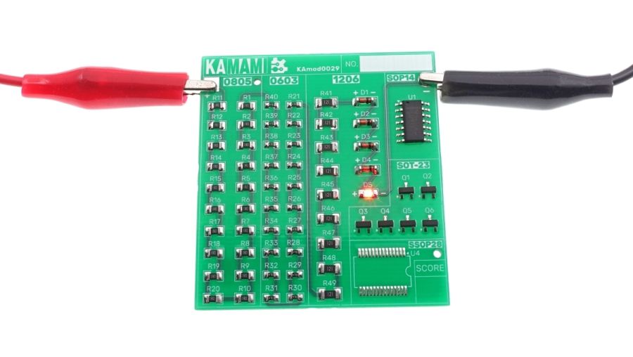
The final effect of correctly soldered resistors and diodes (the integrated circuit and transistors do not affect the operation) is the lighting of the red LED. To check the final effect, simply connect a voltage from the range of 5...12 VDC to the points marked "+" (next to the 0805 marking) and the point "–" (next to the SOP14 marking).

Basic features and parameters
- Single-sided printed circuit board with solder mask
- 20 x resistor [1 Ohm] in SMD housing size 0805
- 20 x resistor [47 Ohm] in SMD housing size 0603
- 9 x resistor [120 Ohm] in SMD housing size 1206
- 4 x LL4148 diode in SOD80 housing
- 1 x red LED diode in 0805 housing
- 6 x BC847 transistor in SOT-23 housing
- 1 x integrated circuit in SMD housing SOP14 raster 1.27mm (LM339 or similar)
View of the assembled set

View of the assembled kit with the power supply attached
To check if the resistors and diodes have been properly soldered (the integrated circuit and transistors do not affect the operation) and the system works correctly, follow a few simple steps:
- Connecting the power supply: Prepare a power supply that can supply voltages in the range of 5 to 12 VDC. Make sure that its poles are marked correctly. The point marked "+" should be connected to the positive pole of the power supply, and the point "-" to its negative pole.
- Checking the soldering: Before connecting the power supply, carefully check the connections: make sure that the components are properly soldered, there are no short circuits, and the solders are clean and strong.
- Connecting the power supply: After making sure that everything is OK, connect the power supply to the "+/-"
- "+" points (next to the 0805 marking) and the "–" point (next to the SOP14 marking).
- Observing the operation: After connecting the power supply, observe the LED: if the assembly was done correctly, the LED should light up red.
