KAmodESP32 POW RS485
From Kamamilabs.com - Wiki

Description
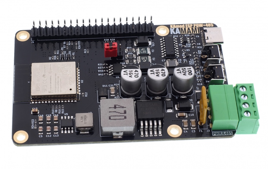
KAmodESP32 POW RS485 - Evaluation board with ESP32-WROOM Wi-Fi module, RS485 interface and efficient power supply system.
The KAmod ESP32 POW+RS485 board contains the ESP32-WROOM module enabling communication in a 2.4 GHz Wi-Fi wireless network. A USB-UART converter with a USB-C connector was used to program ESP32. The module is connected to the RS485 interface - a popular solution in home and industrial automation, enabling communication via a 2-wire twisted pair, e.g. in the MODBUS standard. The board is complemented by an efficient power supply system that operates at an input voltage of 8 to 32 V, and provides stabilized voltages of 5 V and 3.3 V with significant current efficiency. The board's design corresponds to the Raspberry Pi SBC family - it has dimensions of 81x56 mm, and all important I/O ports and supply voltages are led out on a characteristic 40-pin connector.
Basic parameters
- ESP32-WROOM module enabling communication in a Wi-Fi network in the 2.4 GHz band
- Integrated UART-USB converter with USB-C connector enabling programming of the ESP32 system
- RS485 interface for Half-duplex communication with a maximum speed of 1 Mbps
- Maximum number of devices connected to the RS485 bus: 64
- Adapted to a supply voltage in the range of 8...32 V
- Provides a stabilized voltage of 5.1 V with a continuous current of up to 3 A and a short-term current of up to 5 A
- Provides a stabilized voltage of 3.3 V with a continuous current of up to 1 A and a short-term current of up to 2 A
- Overvoltage, overload protection and thermal
- All important I/O ports and supply voltages have been brought out to the 40-pin connector in the Raspberry Pi standard
- Board dimensions: 81x56 mm, height approx. 20 mm
Standard equipment
| Code | Description |
|---|---|
| KAmod ESP32 POW+RS485 | Assembled and launched module |
Electrical diagram
ESP32 module
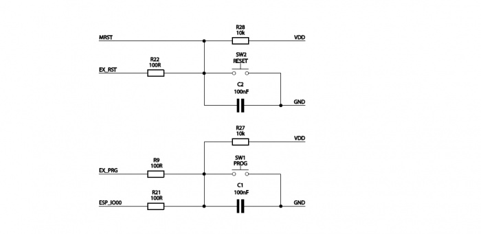
Elements responsible for reset and programming functions
Connector GPIO
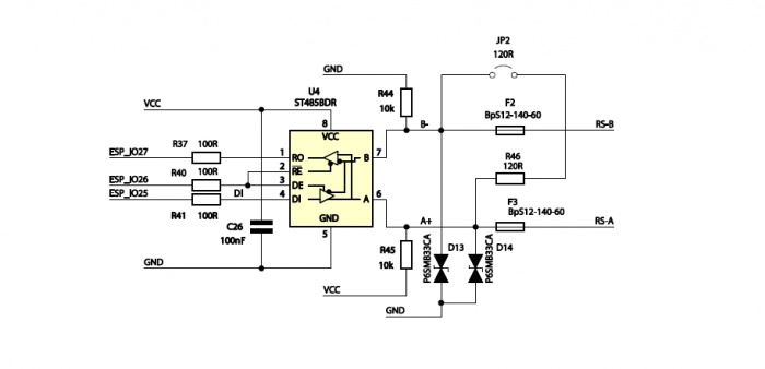
RS485 interface
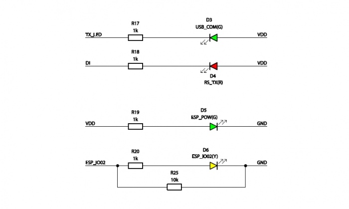
Signaling diodes
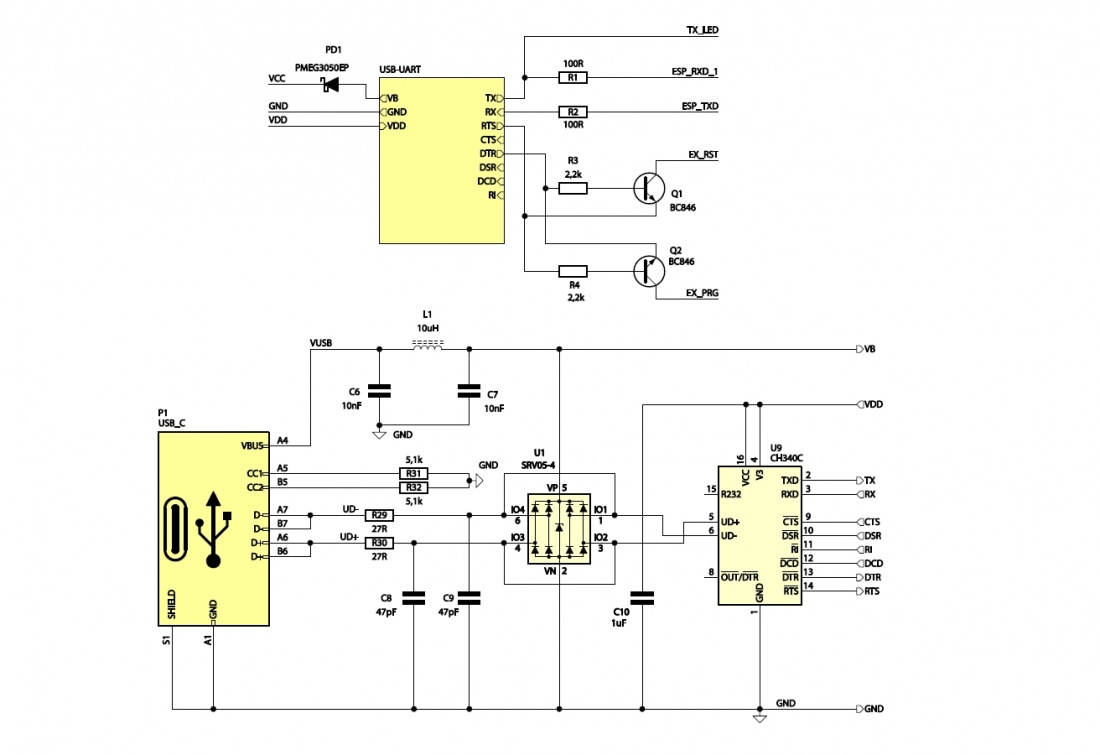
USB-UART interface
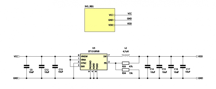
Power block with voltage 5 V

3V Power Block
Power Connector
| Connector | Function |
|---|---|
| POW&485
Phoenix MC3.81 mm |
|
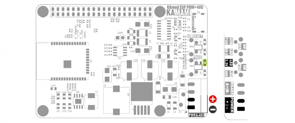
The POW&485 connector (J3) allows you to connect a direct current (DC) voltage from the range of 8...32 V, from which a voltage of 5.1 V is generated to power all components of the board. When connecting voltage to the POW&485 connector, pay attention to its correct polarity. The marking on the bottom of the board: POWER --|+ indicates the correct polarity of the power supply:
- -- - contact no. 1 is ground, negative power supply pole (GND),
- + - contact no. 2 is the input of the positive power supply pole.
Connecting a power supply with parameters sufficient to obtain a voltage of 3.3 V will be indicated by the lighting of the D3 LED. Do not connect a voltage above 34 V. The module contains overvoltage protection that will disconnect the power supply at a voltage higher than approx. 34 V. The connected power source should have adequate power. In order for the module to operate with all parameters (5.1 V / 5 A), the power of the power source should not be less than 30 W. Connecting a power supply with lower power will result in a lower value of the maximum current in the 5 V and 3.3 V voltage circuit.
RS485 interface
| Connector | Function |
|---|---|
| POW&485
Phoenix MC 3.81 mm |
|
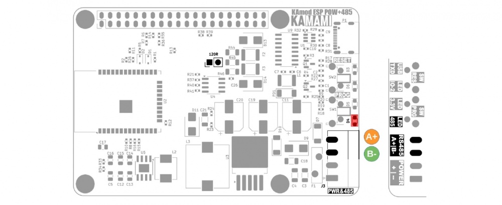
A complete RS485 interface circuit has been implemented on the KAmod ESP32 POW RS485 boardwith overvoltage protection elements. The ST485 system was used as the controller, which allows for the connection of up to 64 devices, works in half-duplex mode, and communicates at a maximum speed of 1 Mbps. Sending data to the bus is signaled by the flashing of the D4 LED.
The RS485 interface connection with the ESP32 module is as follows:
| RS485 signal | ESP32 module output |
|---|---|
|
|
The transmission medium is a 2-wire twisted pair, which should be connected to the POW&485 connector (J3):
- B-, pin no. 3, negative pole of the RS485 bus,
- A+, pin no. 4, positive pole of the RS485 bus.
It must also be ensured that all devices on the bus are connected to a common ground/earth. The RS485 bus specification requires that all connections form a line without branches and loops, and 120 Ω resistors should be connected at its ends, which act as so-called bus terminators. There is a suitable resistor on the KAmod ESP32 POW RS485 board, which can be connected to the bus by placing a jumper on the pins marked 120R.
USB Interface
| Connector | Function |
|---|---|
| P1
USB-C |
|
The P1 USB-C connector is connected to the CH340 controller, which performs the functions of a USB-UART converter. The UART interface can be used in the target application, but it is also used to program the ESP32 module. The programming process can be completely automatic, because the CH340 controller controls the key pins of the ESP32 module (GPIO0 - Boot Select and EN - Chip Power-up).
The signal connections between CH340 and ESP32 are as follows:
| CH340 controller signal | ESP32 module pinout |
|---|---|
|
|
The TXD line is connected to an LED (D3), which signals the reception of data from the USB interface. If a USB-UART converter is used in the target application, it is necessary to ensure that the DTR and RTS lines remain unsupported (Handshaking: None).
The USB-C connector can be used as an alternative power input for the KAmod ESP32 POW RS485 board, but then the power supply circuit parameters will not be met. The voltage on the 5 V line will be lower and will be about 4.5 V; the voltage on the 3.3 V line should not change; the current efficiency of the 5 V and 3.3 V voltages will be much lower and will depend on the power supply used on the USB-C connector.
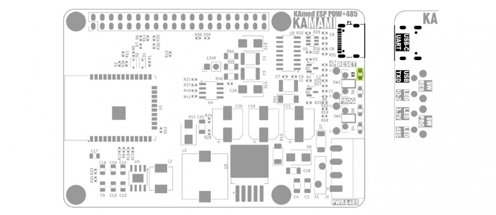
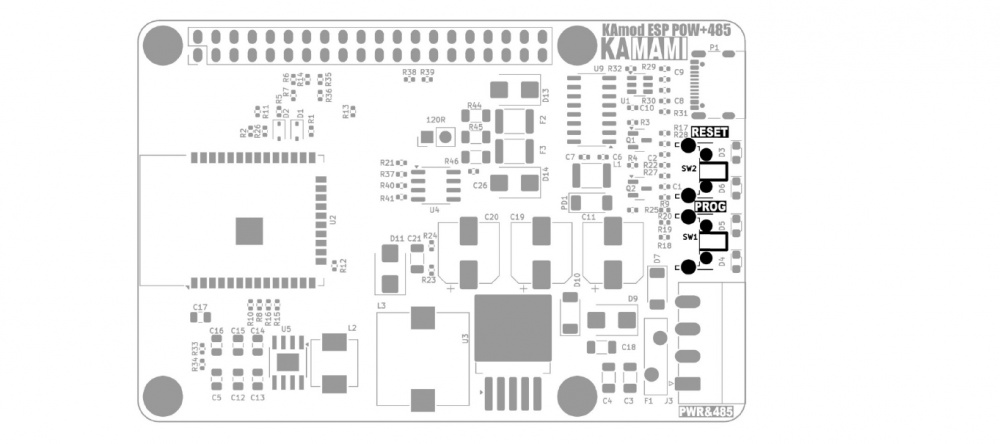
Reset and programming buttons
| Component | Function |
|---|---|
|
|
The RESET button allows you to restart the ESP32 module. It is connected to the EN (Chip Power-up) line of the ESP32 module.
The PROG button allows you to enter the ESP32 module into programming mode. Then you should press the RESET button, then, while holding down RESET, hold down the PROG button and then release RESET, while still holding down PROG for a moment. This functionality can be useful when for some reason the programming mode will not be started automatically via the USB-UART converter.
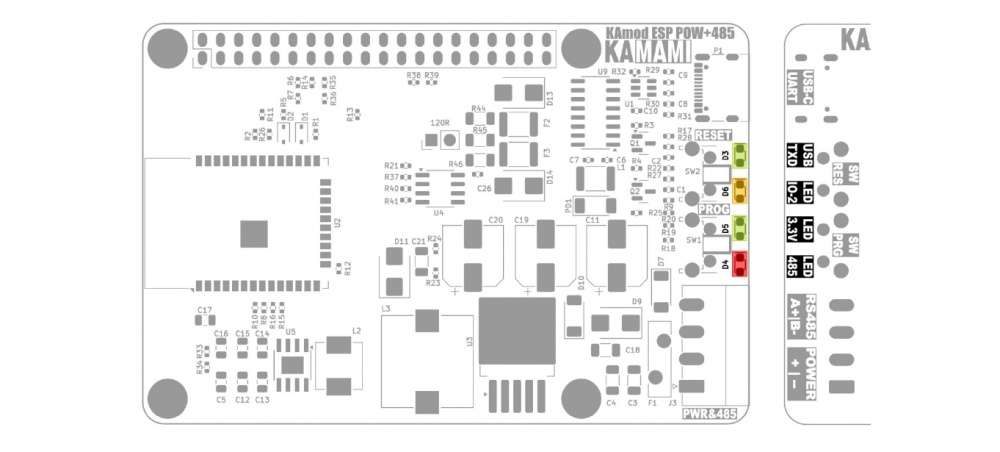
Indicator lights
| Component | Function |
|---|---|
|
|
There are 4 LEDs on the KAmod ESP32 POW RS485 board, which indicate the operation of various components - according to the table above.
Diode D6 (LED IO-2) is connected to the GPIO2 pin of the ESP32 module. Its lighting requires a software setting of the high state on the pin GPIO2
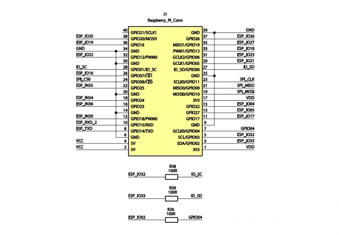
GPIO connector in the RPi standard
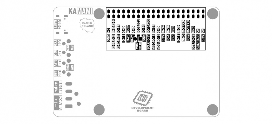
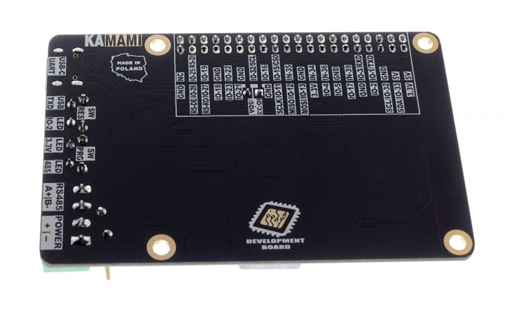
The GPIO connector (J1) in the Raspberry Pi standard contains 40 pins, to which the 5 V, 3.3 V, GND power lines and GPIO pins of the ESP32 module are connected. The UART (TXD, RXD), I2C (SDA, SCL) and SPI (MOSI, MISO, SCLK, CS0) interface pins have been arranged as in the Raspberry Pi family boards.
A detailed description of the pins and their functions is shown in the drawing and table below:
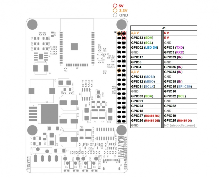
The description of the pins is also provided on the bottom of the KAmod ESP32 POW RS485 board:
Notes on signals output to the GPIO connector
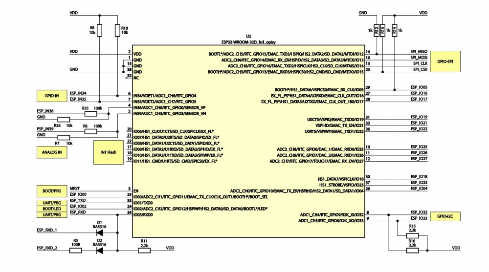
- GPIO ports 34, 35, 36 and 39 of the ESP32 module can only work as digital or analog inputs - they have been marked with the IN symbol.
- GPIO ports 34 and 35 have been equipped with 10k pull-up resistors.
- GPIO ports 36 and 39 have been equipped with voltage dividers (100k/10k), thanks to which a voltage of maximum 35 V can be connected to them.
- GPIO ports 32 and 32 have been adapted to the functionality of the I2C bus and contain 2.2k pull-up resistors.
- GPIO1 and GPIO3 ports act as a UART interface and have been connected to the USB-UART converter module and in parallel to the GPIO J2 connector. The UART interface sends/reads data to/from the GPIO J2 connector and the USB-UART converter simultaneously.
Dimensions
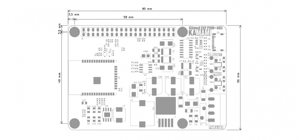
The dimensions of the KAmod ESP32 POW RS485 board are 81x56 mm. The maximum height is approx. 20 mm. There are 4 mounting holes with a diameter of 3 mm on the board, arranged similarly to those on boards from the Raspberry Pi family.
Test program
The test program code is below, you can compile it in the Arduino environment.
#include <WiFi.h>

#include  <NetworkClient.h>

#include <WiFiAP.h>

#include <HardwareSerial.h>


#define  LED_PIN 2


//Server

const char *ssid = "KAmodESP32";
const char *password = "12345678";

NetworkServer server(80);
IPAddress AP_LOCAL_IP (192, 168, 1, 1);

IPAddress AP_GATEWAY_IP (192, 168, 1, 254);

IPAddress AP_NETWORK_MASK (255, 255, 255, 0);
//RS485

#define RS485_RXD 27 //RO PIN

#define RS485_TXD 25 //DI PIN

#define RS485_RE_DE 26 //RE & DE PIN

#define RX_BUFF_SIZE 64

HardwareSerial RS485Port(2);
void setup() {
 //Serial
 Serial.begin (115200);
 Serial.println ("Hello. Configuring access point...");
 //Server
 WiFi.softAPConfig(AP_LOCAL_IP, AP_GATEWAY_IP, AP_NETWORK_MASK);
 if (!WiFi.softAP(ssid, password)) {
   log_e("Soft AP creation failed.");
   while (1);
 }
 IPAddress myIP = WiFi.softAPIP();
 Serial.print("AP IP address: ");
 Serial.println(myIP);
 Serial.print("AP MAC address: ");
 Serial.println(WiFi.softAPmacAddress());
 server.begin();
 //RS485
 //pinMode(RS485_RE_DE, OUTPUT);
 //digitalWrite(RS485_RE_DE, LOW);
 RS485Port.setPins(RS485_RXD, RS485_TXD, RS485_RE_DE);
 RS485Port.setHwFlowCtrlMode(UART_HW_FLOWCTRL_CTS);
 RS485Port.setMode(UART_MODE_RS485_HALF_DUPLEX);
 RS485Port.begin(115200, SERIAL_8N1, RS485_RXD, RS485_TXD);
 RS485Port.println("RS485 Hello");
 //LED
 pinMode(LED_PIN, OUTPUT);
 for(int i=0; i<10; i++){
   digitalWrite(LED_PIN, HIGH);
   delay(200);
   digitalWrite(LED_PIN, LOW);
   delay(200);
 }
}

void loop() {
Networkclient client = server.accept();
if (client) {
 Serial.println("********New client********");
 String currentLine = "";
 while (client.connected()) {
  if (client.available()) {
   char c = client.read();
   Serial.write(c);
   if (c == '\n') {

    if (currentLine.length() == 0) {
     client.println("HTTP/1.1 200 OK");
     client.println("Content-type:text/html");
     client.println();
     client.println("Click <a href=\"/H\">here</a> to turn ON the LED.<br>");
     client.println("Click <a href=\"/L\">here</a> to turn OFF the LED.<br>");
     client.println("Click <a href=\"/RS485\">here</a> to write to RS485.<br>");
     client.println();
     break;
    } else {
     currentLine = "";
    }
   } else if (c != '\r') {
    currentLine += c;
   }
   //if (currentLine.endsWith("GET /H")) {
   if (currentLine.indexOf("GET /H") >= 0) {
    digitalWrite(LED_PIN, HIGH);
   }
   //if (currentLine.endsWith("GET /L")) {
   if (currentLine.indexOf("GET /L") >= 0) {
    digitalWrite(LED_PIN, LOW);
   }
   if (currentLine.endsWith("GET /RS485")) {
    RS485Port.println("You send message via RS485");
   }
  }
 }
 client.stop();
 Serial.println("********Client Disconnected********");
} else {
 RS485Port.println("Tick...");
 delay(1000);
}
}
The test program configures the hardware UART 2 interface to work as an RS485 interface with hardware control of the transmission direction:
#define RS485_RXD 27 //RO PIN

#define RS485_TXD 25 //DI PIN

#define RS485_RE_DE 26 //RE & DE PIN

#define RX_BUFF_SIZE 64
HardwareSerial RS485Port(2);

...

RS485Port.setPins(RS485_RXD, RS485_TXD, RS485_RE_DE);

RS485Port.setHwFlowCtrlMode(UART_HW_FLOWCTRL_CTS);

RS485Port.setMode(UART_MODE_RS485_HALF_DUPLEX);

RS485Port.begin(115200, SERIAL_8N1, RS485_RXD, RS485_TXD);

RS485Port.println("RS485 Hello");
Moreover, the test program runs the ESP32 module in access point mode and as a www server:
const char *ssid = "KAmodESP32";

const char *password = "12345678";
NetworkServer server(80);

IPAddress AP_LOCAL_IP(192, 168, 1, 1);

IPAddress AP_GATEWAY_IP(192, 168, 1, 254);

IPAddress AP_NETWORK_MASK(255, 255, 255, 0);
WiFi.softAPConfig(AP_LOCAL_IP, AP_GATEWAY_IP, AP_NETWORK_MASK);

if (!WiFi.softAP(ssid, password)) {

log_e("Soft AP creation failed.");

while (1);

}

IPAddress myIP = WiFi.softAPIP();

Serial.print("AP IP address: ");

Serial.println(myIP);

Serial.print("AP Mac Address: ");

Serial.println(WiFi.softAPmacAddress());

server.begin();
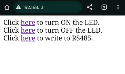
After running the test program a Wi-Fi network will be created called (SSID): KAmodESP32 with the password: 12345678. Use your smartphone to join this network and then enter the IP address of the website in your web browser: 192, 168, 1, 1. It will display a very simple website that will allow you to control the D6 LED or send a simple message via the interface RS485:
