KAmodRPI RTC
From Kamamilabs.com - Wiki

Description
KAmodRPI RTC is a precise real-time clock module - RTC, designed for Raspberry Pi series computers. It is based on the DS3231 system, which has been connected to a battery that supports its operation in the event of a main power failure. Communication with the RTC clock takes place via the I2C interface.
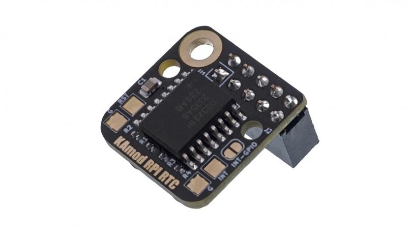
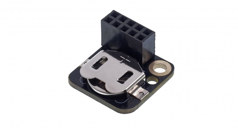
The DS3231 system is a complete RTC clock, which is distinguished by high precision in time measurement. Excellent parameters were obtained by integrating a quartz resonator in the structure of the system and using temperature compensation. There is a socket on the board for a CR1220 battery, which allows the clock to operate even in the absence of main power. The supply voltage required for correct operation is in a wide range of 2.3….5.5 V.
Basic parameters
- Based on the DS3231 RTC clock system
- Clock with integrated quartz resonator and temperature compensation
- The time measurement error declared by the manufacturer of the DS3231 system does not exceed 2 minutes per year, when operating at a temperature in the range of -40...+85 ºC
- Calculates seconds, minutes, hours, days of the week, months and year
- Communication via the I2C interface (400 kHz)
- Includes a socket for a CR1220 backup battery
- Current consumption from the backup battery does not exceed 0.1 uA
- Optional interrupt output (INT) / rectangular signal (SQW)
- Optional reset output activated by a low supply voltage level (RST)
- Requires a power supply with a voltage in the range of 2.3….5.5 V
- Board dimensions 21x20 mm, height approx. 8 mm (without goldpin socket)
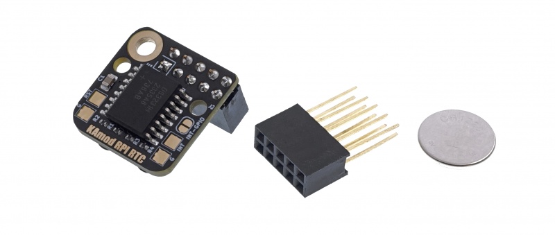
Standard equipment
| Code | Description |
|---|---|
|
|
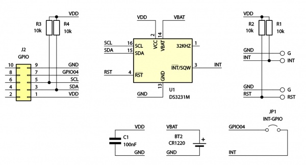
Electrical diagram
Communication connector compatible with Raspberry Pi
| Label | Function |
|---|---|
| J2
Goldpin socket |
|
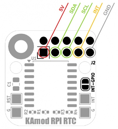
The signals on the communication connector have been arranged to correspond to the signals on the GPIO connector used in Raspberry Pi boards. The KamodRPI RTC module occupies only the first 10 pins of the 40-pin GPIO connector. The functions of the signals on the J2 connector are as follows:
- pin no. 1: +5V - power input with a voltage of 2.3...5.5 V;
- pin no. 3: SDA - I2C interface data line;
- pin no. 5: SCL – I2C interface clock line;
- pin no. 7: INT – optional INT interrupt output or SQW square-wave signal. The signal is available only after making a tin drop jumper on the pads marked INT-GPIO and goes to the GPIO04 port on the Raspberry Pi board;
- pin no. 9: GND – power supply ground;
- pin no. 2, 4, 6, 8, 10: pins are not connected.
Backup battery
| Description | Function |
|---|---|
| BT1 |
|
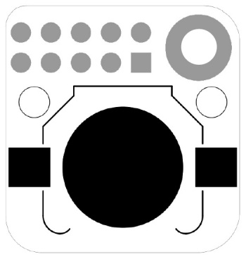
The battery socket is located on the bottom side of the module board. The current consumption from the battery does not exceed 0.1 uA, which allows the clock to operate correctly for many years.
Additional features
| Description | Function |
|---|---|
| JP1 INT-GPIO |
|
| INT, G |
|
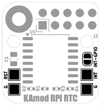
| RST, G | * The pad marked RST is the output that resets the activeane low supply voltage. The threshold is set to about 2.57 V. The pad marked G is ground. |
Detailed information on the functionality and configuration of additional pins can be found in the DS3231 documentation.
Dimensions
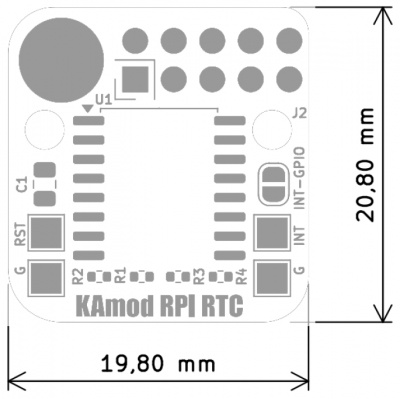
The dimensions of the KAmodRPI RTC module are about 21x20 mm, and the height without the connector is about 8 mm. The module is compatible with Raspberry Pi 5 boards and earlier versions of Raspberry Pi. Additional holes have been placed on the board, which may be useful for non-standard applications of the RTC module.
Running the module with Raspberry Pi 5
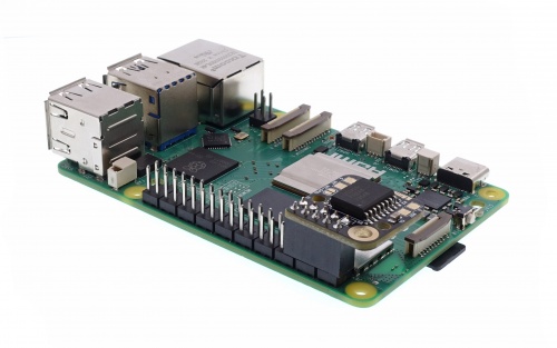
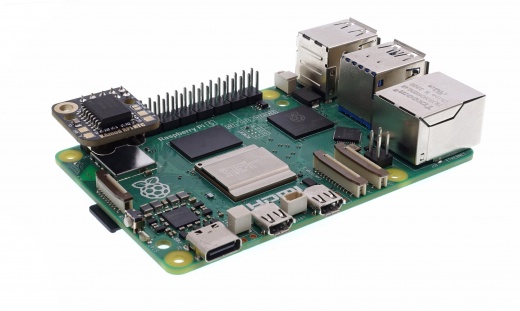
The KamodRPI RTC module is mounted on the first 10 pins of the GPIO connector of the Raspberry Pi computer as shown in the photos below:
 |
 |
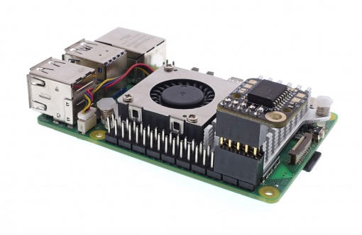
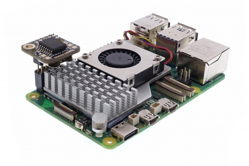
If the Raspberry Pi computer is equipped with a radiator, the KAmodRPI RTC module should be mounted using an additional female-male connector. No element of the module, especially the battery basket, can touch the radiator. The connection should be made as in the photo:
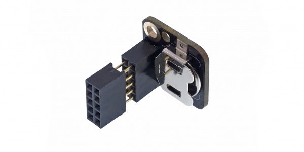
In this configuration, the KAmodRPI RTC module is placed above the radiator and the entire set can operate properly.
 |
 |
Configuring the I2C bus*
* the described procedures apply to the Raspberry Pi 5 computer
The first step will always be refreshing the repositories and software packages. We open the console, e.g. by pressing the key combination Ctrl+Alt+T, and then enter the commands:
sudo apt-get update
sudo apt-get upgrade
Now we will install a software package that makes it easier to work with the I2C interface. To do this, type the command:
sudo apt-get install i2c-tools
The next task we need to perform is to enable the I2C bus controller. We run the Raspberry Pi configurator with the command:
sudo raspi-config
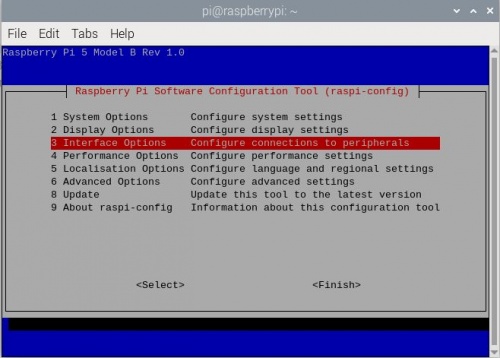
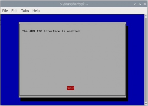
We select option 3 (Interface options), and then select option I5 (I2C). After confirming all changes, we will see a message that the I2C interface is ready.
At this point, using the i2c-detect program we can check what devices have been connected to the I2C bus. We enter:
i2cdetect -y 1
The effect will be similar to the one shown below:
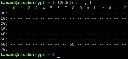
This means that there is a device on the I2C bus with address 68 (hex) - this is the address of the DS3231 chip.
Preparing the Raspberry Pi system*
* the described procedures apply to the Raspberry Pi 5 computer
We start preparing the system by editing the /boot/firmware/config.txt file (in older versions of the Raspberry Pi operating system this is the /boot/config.txt file). To do this, type the command:
sudo nano /boot/firmware/config.txt
At the end of the existing content, add the line:
dtoverlay=i2c-rtc,ds3231
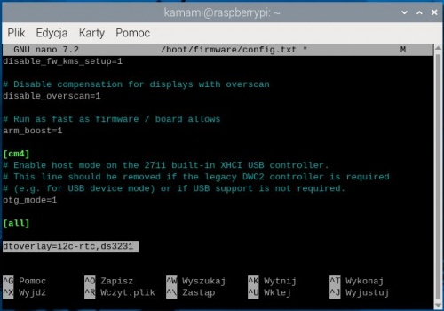
Then save the changes with Ctrl+O and close the editor with Ctrl+X. We restart the system, e.g. by typing:
reboot
After restarting the system, we check the effectiveness of the changes by typing the command:
i2cdetect -y 1
This time the effect should be as follows:
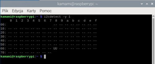
The UU designation, which replaced the previous value of 68, means that the system has correctly communicated with the clock and reserved its address.
Setting and reading from RTC*=
* the described procedures apply to the Raspberry Pi 5 computer
We can check the current system time using the command:
date
To save the current time to the RTC module, enter the command:
sudo hwclock -w
whereas, to read the time from the RTC module, enter:
sudo hwclock -r

The RTC clock can be set to any time value, the command is used for this:
hwclock --set ––date="2024-06-19 12:22:22"
Of course, the date and time can be different but they must be written in the same way as in the above example. Now we can set the time in the system taken from the RTC clock, the command is used for this:
sudo hwclock -s

The system time in Raspberry Pi 5 will be automatically taken from the RTC clock when the computer is started. The time will be automatically corrected when Raspberry Pi gains access to the Internet. Then the RTC time value will also be updated.