KAmod BMP280
From Kamamilabs.com - Wiki

Description
KAmod BMP280 - Precise pressure and temperature sensor with SPI and I2C interface
KAmod BMP280 contains a precise BMP280 sensor manufactured by Bosch Sensortec, which allows for measuring atmospheric pressure and temperature. All key signals of the miniature BMP280 sensor have been output on the module board, which facilitates its use in modular applications. Communication takes place via SPI or I2C interfaces equipped with control voltage translation circuits.
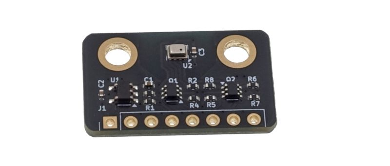
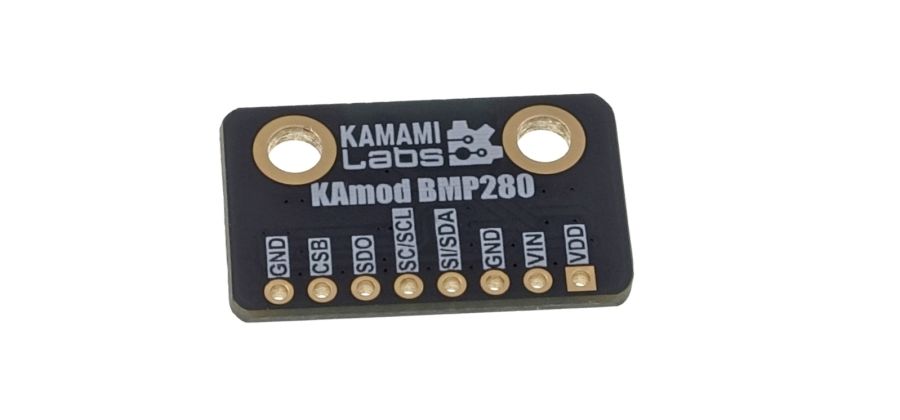
Basic parameters
- Power supply 2...5 V
- Contains a precise BMP280 sensor manufactured by Bosch Sensortec
- Pressure measurement range: 300...1100 hPa
- Temperature measurement range: -40...+85°C
- Allows measurement of atmospheric pressure and temperature
- Communication takes place via SPI or I2C interfaces
- Communication interfaces equipped with voltage translation circuits
Standard equipment
| Code | Description |
|---|---|
| KAmod BMP280 |
|
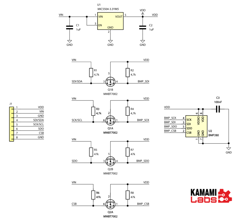
Schematic
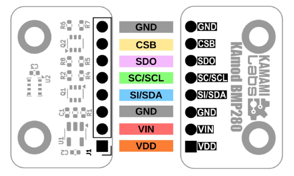
Signal layout on the board
| Marking | Function |
|---|---|
| VIN | Power input 2...5 V, positive pole |
| VDD | Sensor power supply voltage output |
| SI/GND | Power supply ground – negative pole |
| SC/SI/SDA | SPI serial data input or SDA data line for I2C |
| SC/SCL | SPI and I2C clock signal |
| SDO | SPI serial data output or I2C address selection |
| CSB | CS Signal - Chip Select for SPI or I2C interface selection if connected to VDD |
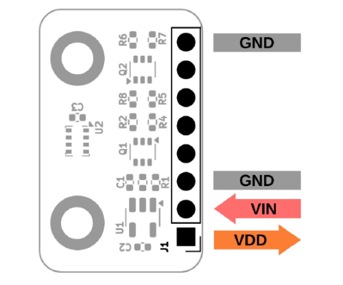
All module signals are led out on a 1-row J1 connector with a 2.54 mm pitch. The arrangement of individual signals is described on the bottom side of the module board (Bottom) and in the drawing:
Communication interfaces
The BMP280 sensor provides two communication interfaces: SPI or I2C. The SPI interface can operate in a 4-wire or 3-wire configuration. Detailed information on communication is included in the BMP280 system documentation.
All control signals of the KAmod BMP280 module are equipped with voltage translation circuits and can work with systems whose interfaces operate with a voltage of 2...5 V.
| 4-wire SPI interface | |
|---|---|
| Marking | Function, connection method |
| VIN | Power input 2...5 V, positive pole |
| GND | Power ground – negative pole |
| SI/SDA | Data input, connect to MOSI SPI uC interface |
| SC/SCL | Clock signal input, connect to SCLK SPI uC |
| SDO | Data output, connect to MISO SPI uC interface |
| CSB | CS - Chip Select signal input, connect to CE SPI uC interface |
| 3-wire SPI interface | |
|---|---|
| Marking | Connection method |
| VIN | Power input 2...5 V, positive pole |
| GND | Power ground – negative pole |
| SI/SDA | Data input/output, connect to SDI/SDO (DI/DO) SPI uC interface |
| SC/SCL | Clock signal input, connect to SCK SPI uC |
| SDO | Not connected |
| CSB | CS - Chip Select signal input, connect to CE SPI uC interface |
| I2C interface | |
|---|---|
| Marking | Connection method |
| VIN | Power input 2...5 V, positive pole |
| GND | Power ground – negative pole |
| SI/SDA | Data input/output, connect to SDA I2C uC interface |
| SC/SCL | Clock signal input, connect to SCL I2C uC |
| SDO | Input, address selection:
|
| CSB | Input, interface selection, for I2C connect to VDD |
Power supply
The KAmod BMP280 module can be powered by a DC voltage of 2...5 V.
The VDD pin provides voltage from the output of the 3.3 V voltage regulator placed on the board. Its value is 3.3 V when the power supply is connected to the VIN pin with a value of 3.5...5 V. However, with a lower power supply, the voltage at the VDD output will be close to the voltage at VIN.
Dimensions
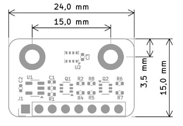
The dimensions of the KAmod BMP280 board are 24x15 mm. There are 2 mounting holes with a diameter of 3.2 mm on the board.
Test program
The test program was written in the Arduino environment for the KAmodESP32 POW RS485 board. The KAmod BMP280 sensor module was connected via the I2C interface.
//example code for KAmodESP32 POW RS485 and KAmod BMP280
//ino board: ESP32-WROOM-DA Module
//additional wires:
//BMP280 SDO -> GND
//BMP280 CSB -> VDD (3.3V)
#include <Wire.h>
#include <SPI.h>
#include <Adafruit_BMP280.h>
//LED
#define LED_PIN 2
#define MY_DELAY 2000
//I2C
#define I2C_SDA 33
#define I2C_SCL 32
//SPI
#define SPI_MOSI 13
#define SPI_MISO 12
#define SPI_SCK 14
#define SPI_CS 15
TwoWire I2CBMP = TwoWire(0);
Adafruit_BMP280 bmp280(&I2CBMP);
int status;
int i;
void setup() {
Serial.begin(115200);
Serial.println("\r\r\rHello. KAmod BMP280 test start");
pinMode(LED_PIN, OUTPUT);
digitalWrite(LED_PIN, HIGH);
I2CBMP.begin(I2C_SDA, I2C_SCL, 100000);
status = 0;
while (status == 0){
status = bmp280.begin(0x76);
Serial.print("SensorID was: 0x"); Serial.println(bmp280.sensorID(),16);
if (!status) {
Serial.println(F("Something wrong..."));
delay(3000);
}
}
bmp280.setSampling(Adafruit_BMP280::MODE_NORMAL, /* Operating Mode. */
Adafruit_BMP280::SAMPLING_X2, /* Temp. oversampling */
Adafruit_BMP280::SAMPLING_X16, /* Pressure oversampling */
Adafruit_BMP280::FILTER_X16, /* Filtering. */
Adafruit_BMP280::STANDBY_MS_500); /* Standby time. */
}
void loop() {
i++;
digitalWrite(LED_PIN, (i&1));
Serial.print(F("Temperature = "));
Serial.print(bmp280.readTemperature());
Serial.print(" *C; ");
Serial.print(F("Pressure = "));
Serial.print(bmp280.readPressure());
Serial.println("Bye");
Serial.println();
delay(MY_DELAY);
}